|
|
- |
|
|
 |
 |
-
Start Project No. 1 (Chapter
step by step exercises).
-
| To
do this week:
Design
Assignments include:
-
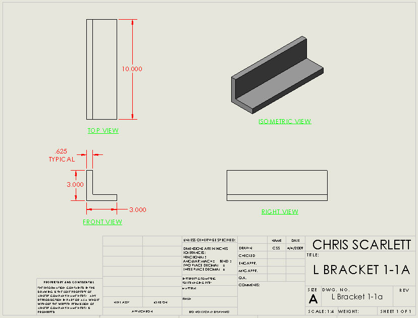
Assignments
1.1a, 1.1i, 1.2a, 1.2f
Four drawings
total. |
These assignments are due
on Friday April 2, on your new drawing template that we will create Thursday
during class. Print out on "A" sized paper (8.5" x 11"), landscape
orientation.
|
- |
|
|
 |
|
-
Start the Project No. 1
models (Chapter step by step exercises).
-
| Due
this week:
Design
Assignments include:
-
Assignments
1.12, 1.14, send these via eDrawings as both a drawing and a part, allow
measurements.
Project
Assignments include:
Plate,
Rod and Guide, print out the Plate and Rod and leave in box.
|
Tuesday's class will start
with criteria on grading. Bring your questions.
We will then proceed to
updating our template files. Updates to these files include:
Drawing (see example below)
-
Reduce the "Drawing No." font
so that the drawing name will fit in the space allocated for it
-
Add information for "Drawn By"
(initials) and "Drawn Date" ("Short Date") in the title block
-
Select the "Third Angle" projection
(as opposed to the "First Angle" default) for drawing views
-
Add View Titles to each of the
views.
-
Change the "Bent Leader" length.
Part
-
Insert "Company Name" and "Description"
information in the model properties off of the Pull Down Menu (File, Properties,
Custom Tab).
Start the Project models (Plate,
Rod and Guide) as a series of step by step exercises in the book.
Print out drawings for the Plate and Rod only using your "A sized" drawing
template. We will save the Guide for the Project No. 3 drawing.
Leave these drawings in the box in the lab.
Do Design Assignments 1.12
and 1.14, save as an eDrawing part and drawing, "allow measuring" and send
via email by Friday at 5pm.
|
- |
|
|
 |
|
-
| Due
this week:
Design
Assignments due Friday by 5pm include:
-
3.7 on a
B sized drawing template (one drawing).
|
I will not be here for class
on Tuesday, out sick. Please work on Project's #2 and #3. Use
your class time effectively. Stay and seek or give help to others.
Skip the section on Cosmos Express (pages 2-78 - 2-92).
Also on Thursday I will demonstrate
the assembly of the parts for the Guide Rod assembly if needed and start
Project #3.
|
- |
|
|
 |
|
-
| Due
this week:
Project
Assignment:
In
class evaluation on Design Assignment 2.3 at the beginning of class on
Tuesday.
In class
evaluation on the Motion Study for your gear design at the beginning of
class on Thursday.
Design
Assignments due Friday by 5pm include:
-
Gear design,
2 gears and mounting plate as parts on your A sized inch drawing
template.
-
Project
#3 Drawing as described in the book. Do not hand in anything on the
sections for the Exploded Views or Bill of Materials. Cover these
sections while reading and modeling and plan on handing these in at a later
date
|
On Tuesday, an in class evaluation
will be conducted for the Design Assignment 2.3. For this evaluation,
I will be looking for proper assembly techniques with points taken off
for incomplete or missing mating references (as described in the book),
missing parts and mating errors. To get a good grade, build all of
the parts properly (check previous week's markups) and follow the book
covering every step described.
Tuesday's class will follow
up with a demonstration on spur gear design. Refer to the Student
Resources link for instructions on this assignment. Also check the
Gradesheet and click on the tab at the bottom left of your window that
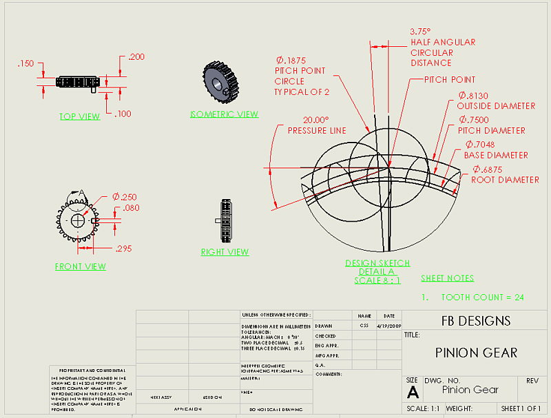
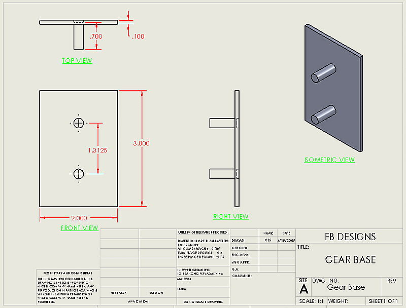
states "Gears" for your design parameters. Every student will have
a different Design Assignment. The values that you will need to get
started include the Gear Ratio, Dimetral Pitch and the number of teeth
on the Pinion Gear. The gears and mounting plate will be modeled
and handed in on Friday as Design Assignment drawings, 3 total (see below).
On Thursday, an in class evaluation on a motion study of these gears will
be conducted similar to Tuesday's evaluation. Check out the link
at "Page of helpful class related links" from the "Student Resources Link"
above for more general information on spur gear design.

|
- |
|
|
 |
|
-
| Important
this week:
Test
on Tuesday, pre evaluation modeling instructions follow below. The
examination portion is closed book, the modeling portion is open book.
Grading
criteria changes for recent assignments follow below.
Design
Assignments due Friday by 5pm include:
-
4.4 and
4.8 as an eDrawing drawing via email.
YASWUG meeting
on Thursday, Oxford Suites, see information at the top of the website. |
Changes to grading criteria
on recent assignments:
-
Project 3
-
For those that missed the first
week deadline you can hand in this Design Assignment by Friday May 1 for
up to 90% of the original potential grade (up to 18 points in lieu of 70%
or 14 points). No redos for this second deadline.
-
For those that handed in this
assignment but would like to improve your grade you can make the corrections
noted on the markup and hand it back in for up to 100% of the original
potential grade.
-
For those that handed in this
assignment and received a good grade (16 points or better) will get an
automatic 20% (or 4 points) added to your grade without any additional
work.
-
In Class Evaluation for Design
Assignment 2.3. Re-evaluation on Tuesday May 5th.
-
For those that missed this evaluation
last Tuesday you can demonstrate this to me for up to 80% (or 16 points)
of the original potential grade.
-
For those that were present
for the original evaluation you will get 10% (2 points) added to your grade.
-
In Class Evaluation for the
Gear Motion Study. Re-evaluation on Tuesday May 5th.
-
For those that missed this evaluation
last Thursday you can demonstrate this to me for up to 80% (or 16 points)
of the original potential grade.
-
For those that were present
for the original evaluation but did not have it done correctly you can
demonstrate this to me for up to 90% (or 18 points) of the original potential
grade.
-
For those that were present
for the original evaluation and got a full grade (16 points or more) you
will get 20% (4 points) added to your grade.
Test on Tuesday, details
for the pre-evaluation model follow below.
The model portion of the
test will be a garden cart. Yes, a glamorous, sporty, to be envied
by all type of Garden Cart. Units in inches to 3 digits after the
decimal. All parts are plain carbon steel. Prior to the test
you should build the following parts and assembly (or you will not have
enough time on Tuesday):
Cart Side and Floor.
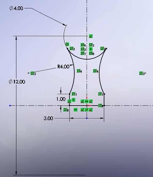
Sketch the following on
the Front Plane before extruding it 43.731 inches. The side is 30
inches at its maximum minus the top lips and the height is 12 inches at
its maximum:
 More notes on the above sketch:
The Origin is on the exterior line, the fillet radius on the bottom corners
are measured from the outside, the fillet radius on the upper lip is on
the inside, the upper lip is 1.50" from the inside of the cart to the end
(use the offset sketch entity). Use plain carbon steel for material
and find the thickness of 10 gauge sheet steel for the thickness.
The result should similar to the image below:
More notes on the above sketch:
The Origin is on the exterior line, the fillet radius on the bottom corners
are measured from the outside, the fillet radius on the upper lip is on
the inside, the upper lip is 1.50" from the inside of the cart to the end
(use the offset sketch entity). Use plain carbon steel for material
and find the thickness of 10 gauge sheet steel for the thickness.
The result should similar to the image below:

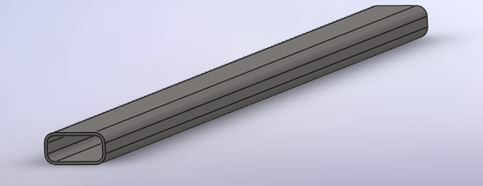
Cart Floor Support, Side.
Sketch the following on
the Front Plane before extruding it 44 inches.
 More notes on the above sketch:
Start with a Center Rectangle with the above dimensions, fillet the edges
as shown, extrude. The result should similar to the image below:
More notes on the above sketch:
Start with a Center Rectangle with the above dimensions, fillet the edges
as shown, extrude. The result should similar to the image below:
Cart Floor Support, Center.
The sketch for the floor
support in the center is similar to the above but 64 inches long.
There is a hole cut in the front for the Hitch (centered with the Right
Plane).

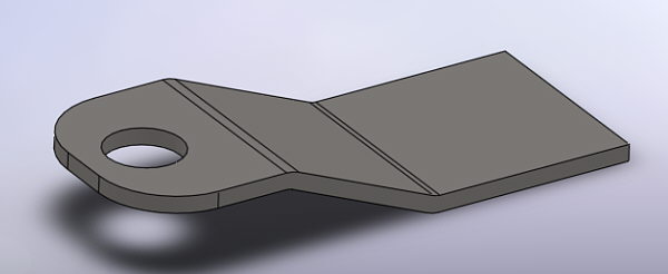
Cart Hitch Mount.
Sketch the following on
the Right Plane. Start with a construction line with the dimensions
and fillets as shown. Offset this line 1/2 the distance of 8 gauge
sheet steel (look this up) on both sides. Extrude it 2 inches.
Place 2 3/4 inch feature fillets on it and a hole in a position similar
to the one sketched for the floor support.
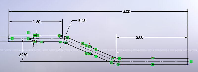 The result should look similar
to the image below:
The result should look similar
to the image below:
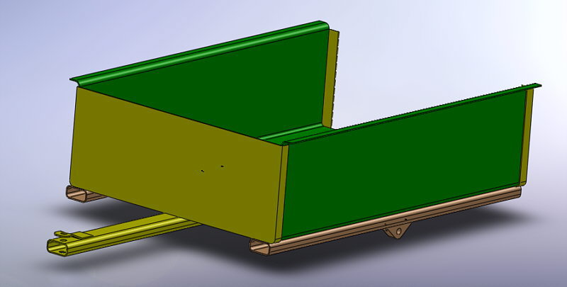
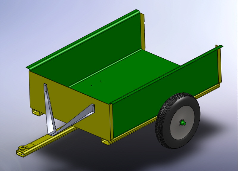
Cart Assembly:
The Cart Assembly (so far)
will look similar to the image below. Part colors are required and
of your choice. The front and rear panels of the cart will be constructed
in class as a class exercise. The wheel mount will be built on your
own during the evaluation. Extra credit is offered for items or features
added that reduce sharp edges on the top lip of the Cart Side and Floor
piece.
 This portion of the test will
require a drawing of the Wheel Mount and an in class evaluation of your
assembly.
This portion of the test will
require a drawing of the Wheel Mount and an in class evaluation of your
assembly.
|
- |
|
|
 |
|
-
| Due
this week:
Re-evaluations
for the two In Class Evaluations for the Gear motion Study and the Assembly
from Design Assignment 2.3 according to the criteria listed in the Week
5 section above.
Design
Assignments due Friday by 5pm include:
-
4.9 as an
eDrawing drawing via email.
-
Project
#4 as a printed "B" sized drawing on two sheets. The Battery and
Battery Plate on one sheet and the Lens and Bulb on the second sheet.
Skip the part on Mold Tools.
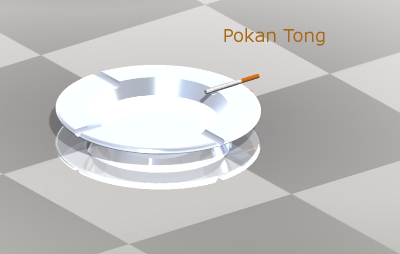
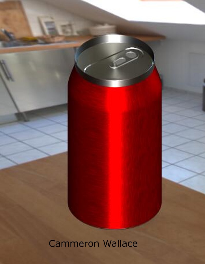
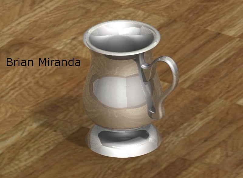
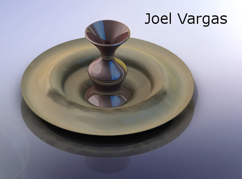
Extra Credit
Assignments due Friday by 5pm may include:
-
PhotoWorks
rendering of all or any combination of the following: cup, challis, vase
and tray using revolved features. Send via email as an eDrawing drawing
and jpg image.
|
Tuesday, we will:
-
Briefly cover the recent examination
and go over the items that will be on the next examination.
-
Re evaluate the two In Class
Evaluations for the Gear Motion Study and the assembly from Design Assignment
2.3 according to the criteria listed in the Week 5 section above.
-
If time permits start Project
4 and extra credit assignments.
-
The extra credit includes rendering
an image in PhotoWorks of your design of all or any combination of the
following: a cup, challis, vase and or a tray or similar objects using
Revolve Features as described in this project. Four maximum.
You will send to me an "A" sized eDrawing drawing with dimensions and a
rendering of the item in PhotoWorks as a JPG file. Save the JPG file
with the highest resolution for more credit (don't send a postage stamp
sized image). The more creativity and effort the more points.
Thursday, we will:
|
- |
|
|
 |
|
-
| Due
this week:
Design
Assignments due Friday by 5pm include:
-
4.6 and
4.7 as a printed drawing in the box. Apply GD&T as described
in class on Tuesday.
-
Design a
Pin with tolerancing on it to fit both Design Assignments.
-
3 drawing
total.
Final Project
Abstract due, one page. Refer to the Student Resources link above
for additional information. |
Tuesday
-
We will briefly cover the Final
Project and abstract due at the end of the week. Additional information
can be found at the Student Resources link above.
-
We will cover a lecture on Geometric
Dimensioning and Tolerancing (GD&T). This is the application
of symbology and text to describe tolerances on features other than just
length that we have been using up to now. For example, these tolerances
may be: perpendicularity of a pin to fit in a slot, parallelism of the
sides of the pin along its length, location tolerance of the axis of the
pin and so forth. The slot will have similar tolerances to ensure
that the item with the slot at its Least Material Condition (LMC) will
accommodate the Pin at its Most Material Condition (MMC). Additional
information, via a section in a text book, can be found at the Student
Resources link above.
-
If there is any time we will
work on the Design Assignments or Project No. 5.
Thursday
-
Hand in your drawings per the
following instructions:
-
By Friday at 5pm.
-
Printed on A sized inch template
-
In the box
-
Units in inches to a precision
of 0.123
-
4.6
-
Make the front virtual plane
datum surface A
-
Make the top virtual plane datum
surface B
-
Make the right virtual plane
datum surface C
-
Apply a bilateral tolerance
on the circle that defines the cylindrical cut for the 1" hole to be between
1.000" and 1.003"
-
Make the position of the cylindrical
cut of the 1" hole to have a geometric tolerance of 0.002" referencing
Datum B and Datum C at the most material condition.
-
Make the position of the cylindrical
cut of the 1" hole to have a geometric tolerance of 0.002" that is perpendicular
to Datum A regardless of feature size.
-
Make the back surface of the
block to have a flatness tolerance of 0.001" to Datum A regardless of feature
size.
-
4.7
-
Make the top virtual plane datum
surface A
-
Make the front virtual plane
datum surface B
-
Make the right virtual plane
datum surface C
-
Apply a tolerance on the circle
that defines the cylindrical cut for the 1" hole to be between 1.000" and
1.003"
-
Make the position of the axis
for the cylindrical cut of the 1" hole to have a geometric tolerance that
is parallel to Datum A and Datum C at the most material condition with
a tolerance of 0.002".
-
Make the inside surface of the
back tab, as seen in the top view, parallel to Datum B with a tolerance
of 0.002" at the most material condition.
-
Pin
-
Make the surface on the bottom
of the head of the Pin Datum A
-
Make the cylindrical circular
extrusion of the pin from the head circular with a tolerance of 0.02"
-
Apply a tolerance on the circle
that defines the cylindrical extrusion of the 1" Pin to be between 0.998"
and 0.992"
-
Make the cylindrical circular
extrusion of the pin from the head perpendicular to Datum A with a tolerance
of 0.003" at the most material condition.
|
- |
|
|
 |
|
-
| Due
this week:
Design
Assignments due Friday by 5pm include:
-
Project
#3, Exploded View and Bill of Materials (BOM)
-
Exploded
view, 2 views on B sized paper, exploded with paths and collapsed assembly.
-
For the
BOM, exploded assembly with paths, balloons and BOM on B sized paper.
-
-
Project
#5, place your parts on B sized drawings in a similar manner as Project
#4. In class evaluation on Thursday for the Flashlight Assembly.
Final Project
Abstract revisions if any. |
Project #5 Drawings, ignore
the section in Project #5 on eDrawings.
Flashlight Part Drawings,
include the O-Ring, Switch and Lens Cap
-
Parts on B sized paper printed
in the lab
-
Units in Inches, precision to
3 decimals
-
Hidden Lines Visible in the
appropriate views
-
The drawing may look similar
to
the following image, create additional views and add additional dimensional
text if it enhances the information.

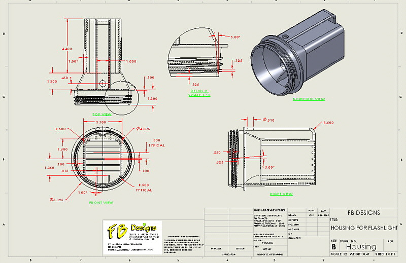
Flashlight Housing Drawing,
include the Flashlight only
-
Parts on B sized paper printed
in the lab
-
Units in Inches, precision to
3 decimals
-
Provide a detail of the threads
from the Top View
-
Hidden Lines Visible in the
appropriate views
-
The drawing may look similar
to the following image, create additional views and add additional dimensional
text if it enhances the information.
|
- |
|
|
 |
|
-
The model portion of the
examination to be evaluated on Tuesday follow below.
From the first examination
you should have the following parts and an assembly as listed below:
Cart Side and Floor
Cart Floor Support, Side
Cart Floor Support, Center
Cart Hitch Mount
Wheel Mount
Cart Assembly
Before getting started on
the new parts listed below fix any problems that you may have had with
the parts and/or assembly from the last examination.
For this examination you
will build the following parts:
Wheel
Tire
Wheel Tire Assembly
Cart Axle
Cart Wheel Spacer
Cart Axle Hub Cap
Cart Front Support
Wheel
Sketch on the front plane
the sketch below. Use the Revolve Boss/Base feature. Material
is stainless, AISI 304. Hint, draw the two centerlines as shown.
Sketch the circle on the top representing the seat for the tire.
Sketch the bottom line on the axis then the side for the hub, then a 3
point arc from the top of the side for the hub with the other end tangent
to the tire seat circle. Mirror the items on one side to the other,
trim out the top portion of the tire seat circle. Using the horizontal
centerline revolve the sketch. When done with the revolve feature
cut a 0.75" hole in the center for the axle.
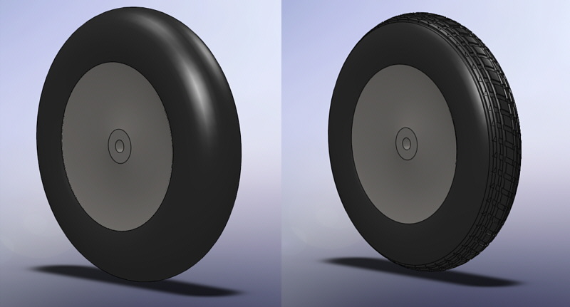
Tire
Sketch on the front plane
the sketch below. Use the Revolve Boss/Base feature.
Material is Rubber. Extra credit for tire treads (sketch cuts in
the sketch shown below and/or sketch a pattern on a plane, use the Offset
from Surface option for an Extrude Cut then apply a Circular Pattern).

Wheel Tire Assembly
Insert both the Wheel and
Tire to the Origin in the assembly.
Cart Axle
Sketch on the right plane,
an axle 0.75" in diameter and 40 inches long (Mid Plane Extrusion).
Material is Plain Carbon Steel.
Cart Wheel Spacer
This item fits between the
Wheel and the Wheel Mount. Design this part so that the wheel does
not interfere with the Cart.
Cart Axle Hub Cap
This item fits on the end
of the axle. Design this part using a sketch and the Revolved Boss
Base feature.
Cart Front Support
This item will be designed
in class using the Loft Feature.
More details will follow
before class on Tuesday.
|
- |
|
|
 |
|
-
| Due
this week:
Final
drawings of your Final Project design printed on A or B sized sheets in
the lab. |
We will go over the test
briefly on Tuesday and will work on the Final Project both on Tuesday and
Thursday.
|
- |
|
|
 |
|
-
Final Project presentations
will be during the Final examination time slot set aside for our class
on Tuesday at 6pm. For those that want to start early I will be in
the lab at 5pm if the lab is available. Please plan on staying for
all of the presentations.
The procedure for your presentation
will be the following:
-
Prior to the class starting,
each student will load their folder of presentation materials and their
SolidWorks files of their project on the desktop of the instructor's computer.
-
Your folder needs to have your
name on it so I can download it and take it home for grading.
-
Once the files are loaded on
the instructor's computer we will start the presentations.
-
Presentations
-
For those that are presenting
during the 5 o'clock hour we will take a break at about 5:50 so that the
rest of the class can load their folders onto the instructor's computer.
-
A presentation schedule is available
at the Student Resource link above.
-
For additional information on
the Final Project visit the links at the Student Resources link above.
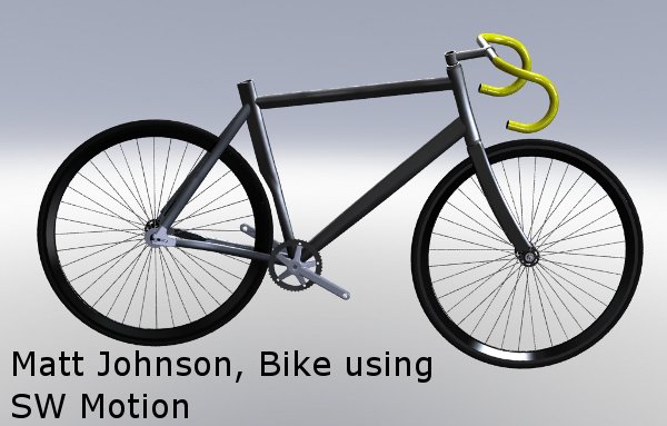
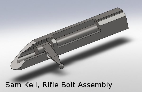
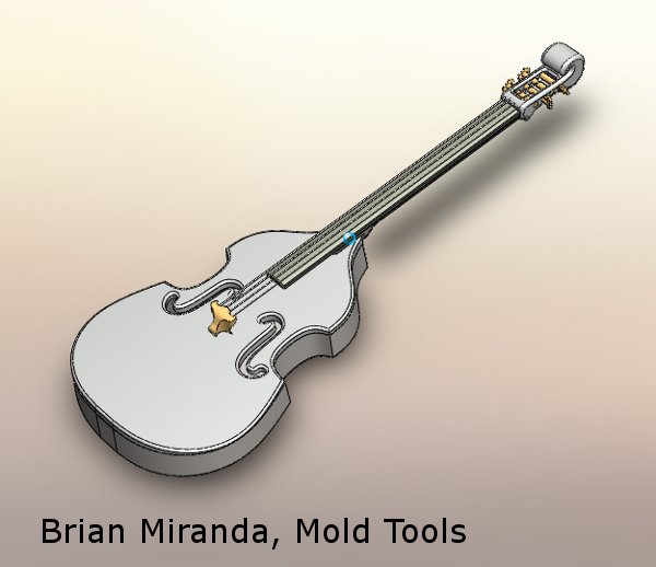
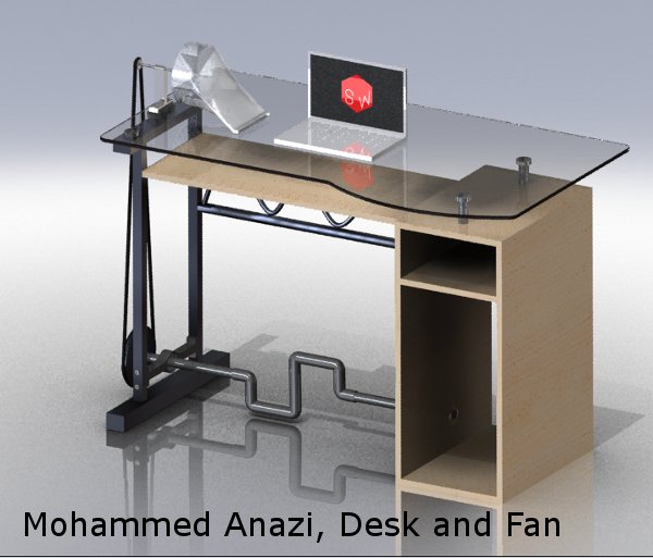
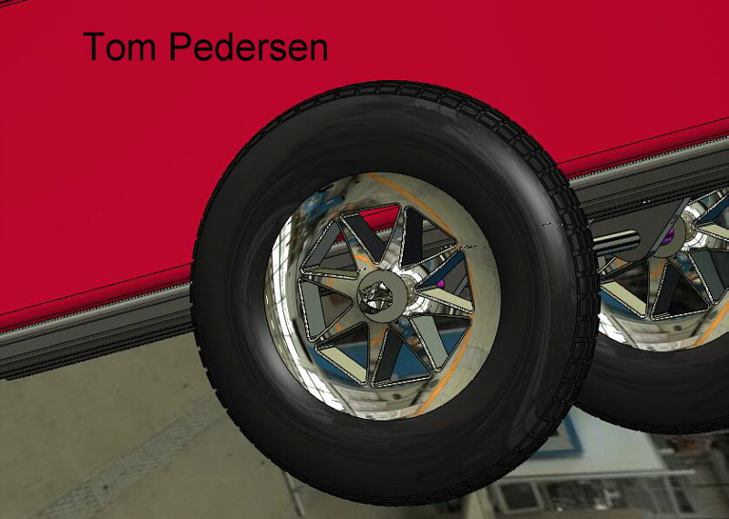
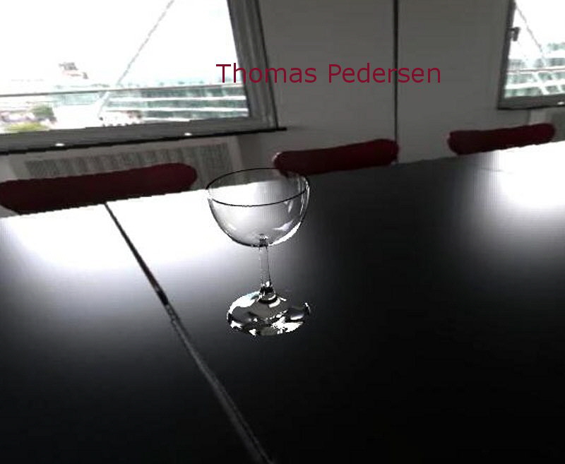
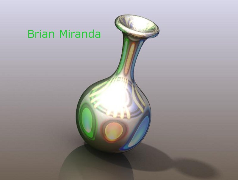
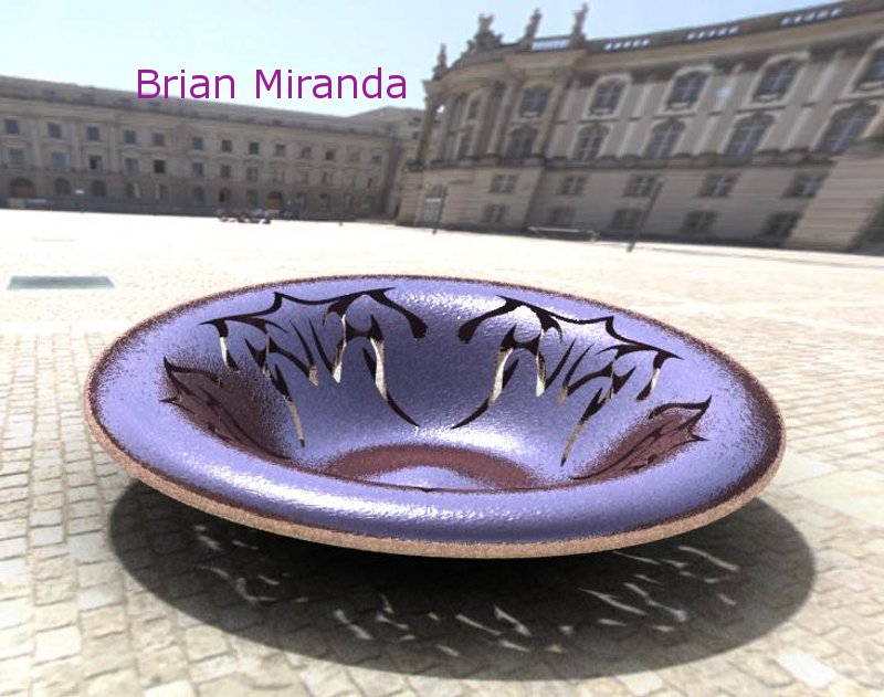
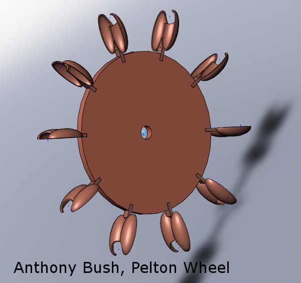
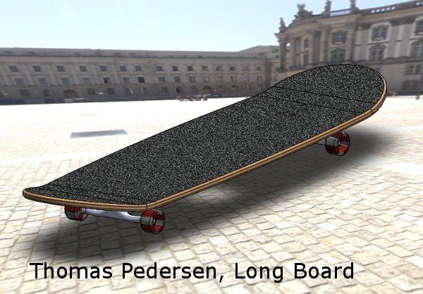
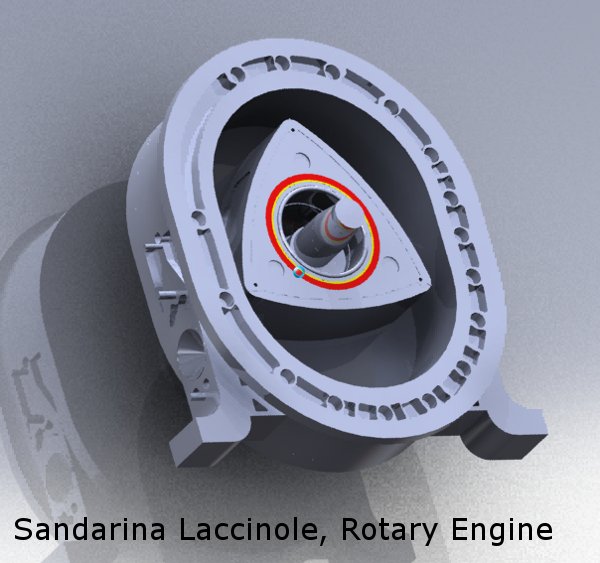
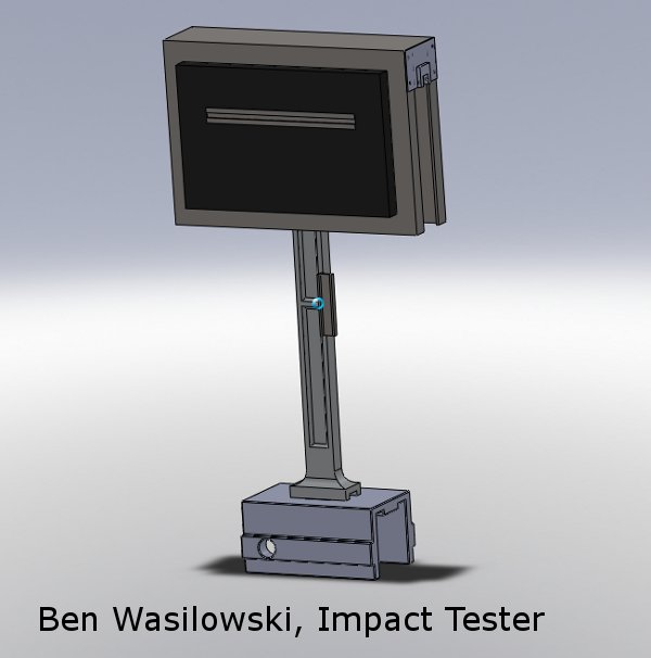
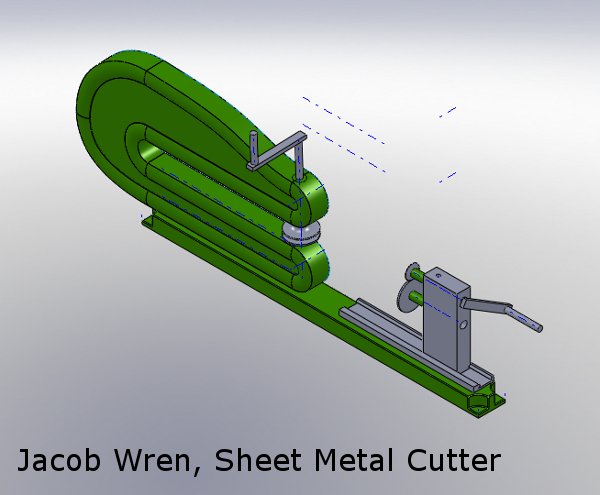
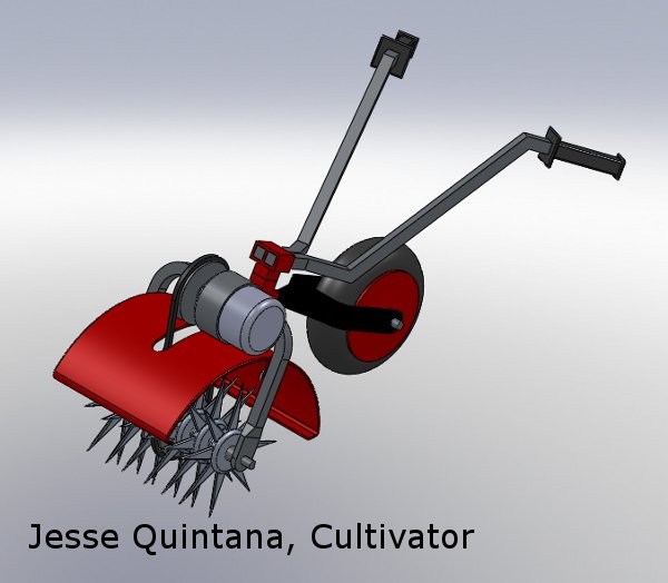
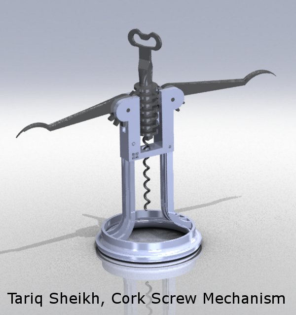
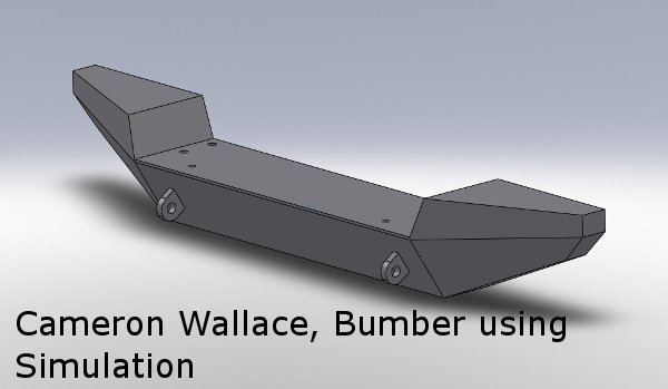
Below are some images and videos
of your completed projects:
-
-
-
-
 -
-
-
-

-

-

-
-
-
 -
-
-
-

-
 -
-

-
-
 -
- |