|
|
- |
|
|
 |
 |
-
Click on the following links:
Trailer
for the Movie "21"
Interview
with Jon Hirschtick, Founder of SolidWorks
Scibd
Biography of Jon Hirschtick, Founder of SolidWorks
Jon
Hirschtick explains his Black Jack Team techniques
Jon
Hirschtick on the Movie "21"
-
| Week
1:
Read
the introductory sections of both textbooks. Also read and model
Lessons 1&2 in the SG textbook and read and model Project 1 in the
ED textbook up to page 1-64. |
|
- |
|
|
 |
|
-
| Week
2:
An evaluation
of 2 of the 4 models that we have modeled so far will be on Tuesday.
Refer to the guidelines below and the Grade Sheet link above and click
on the Week 2 tab for the grading criteria.
Call
me if you have any troubles, do not come to class unprepared!
Assignments
include: The Guide, Axle, Shaft Collar and Flat
Bars in the ED book. Tutor1 and the Door in the SG book.
See
below. |
-
For Tuesday we will have
an evaluation of 2 of the 4 models that we have modeled so far. The
first one will be the Plate with the other either the Receptacle Plate
or Switch Plate. The evaluation criteria will include:
-
Completeness, models are finished
with all of the features shown in the examples or in class. (5 points with
1/2 point off for each missing feature).
-
Dimensions, I will be looking
for proper dimensions on your sketches (2 points with 1/2 point off for
each missing dimension).
-
Fully Defined, your model sketches
will be fully defined (lines are black) (1 point with 1/2 point off for
each under defined line).
-
Feature Names, rename features
to better describe what that feature does (1 point with 1/2 point off for
each unnamed feature). See example below.
-
Origin, the origin will have
to be somewhere placed specifically in the model either in the center of
your object or where the examples in the book show it to be located (1
point).
-
Extra credit, 1/2 point for
each fully defined feature or element.


Assignments:
Complete the Guide, Axle,
Shaft Collar and four configurations of the Flat Bars
(3, 5, 7 and 9) in the ED book. A demonstration on configurations
will be held in class.
Complete Tutor1 and
the Door in the SG book.
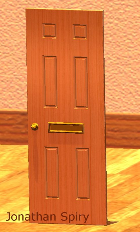
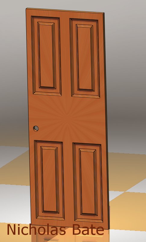
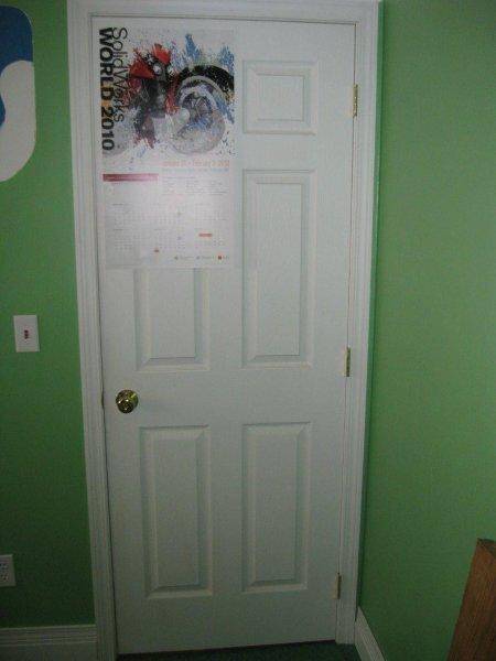
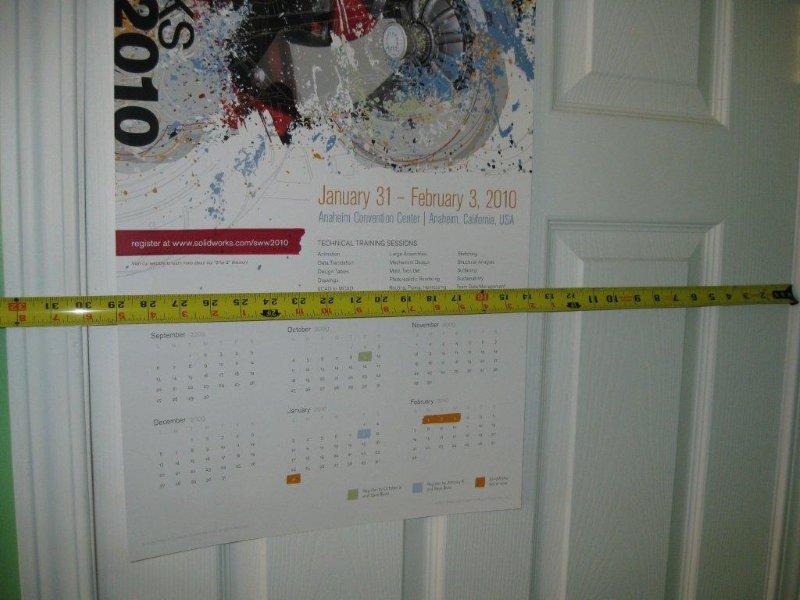
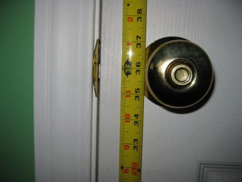
Model a door, any door you
like, in a manner you see fit with at least one door panel feature.
A demonstration on the Sweep Cut feature, which may be used to cut door
panels, will be shown in class.
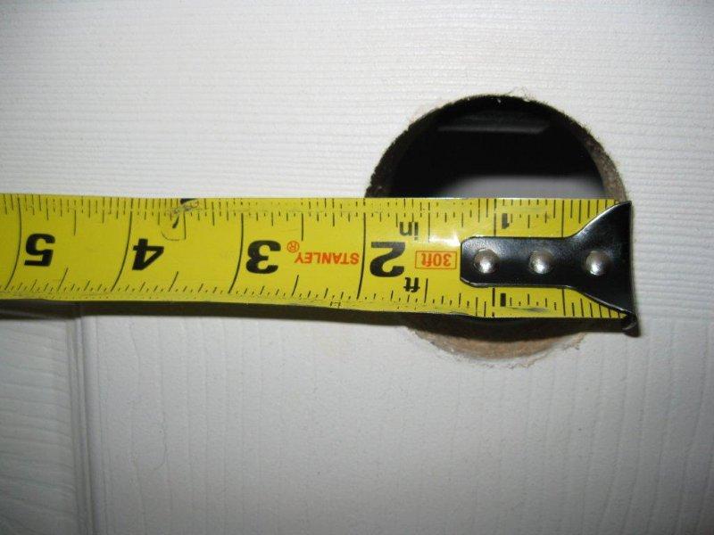
Information on the construction
of a door follows in the images below, my door was 1-3/8" thick:
-
-

-

-
-

-
-
|
- |
|
|
 |
|
-
| Week
3:
Assignments
this week include 5 assemblies to graded in class next Tuesday. Check
the class schedule for details.
A few
students were modeling the Rod from Project 1 in the ED book.
This model is available for download on the Student Resource page for use
in Project 2. |
-
|
- |
|
|
 |
|
-
| Week
4:
We will
cover Drawings this week. As demonstrated on the first day of class
SolidWorks provides a comprehensive way to demonstrate your designs in
a 2D format (drawings on paper). The first task on Thursday will
be to update our new drawing templates using the Tutor2 drawing that we
did in class on Tuesday. Use these updated templates for the drawings
due this week and for the rest of the quarter. For the assignments
this week, follow the Class Schedule. Start with the SG assignments
first then the ED assignments.
All of
the drawing assignments will be due on Friday of Week 5 by 5pm in the "box". |
-
|
- |
|
|
 |
|
-
| Week
5:
Your
first examination will be on Tuesday, including both a written examination
as well as a modeling exercise including parts and an assembly. See
details below.
Drawings
will be due in the "box" by Friday of this week (in lieu of the usual Tuesday
deadline). They will be graded over the weekend and returned on Monday.
Check the "Drawing Guidance" section in the Student Resource section of
the website for grading information.
The grades
for your first examination will be posted this weekend as well as your
drawing assignments due on Friday. A letter grade for the quarter
will also be assigned giving you an opportunity to see where you stand
in class if I had to grade you as of this week. I will be doing this
every week now until the end of the quarter. |
-
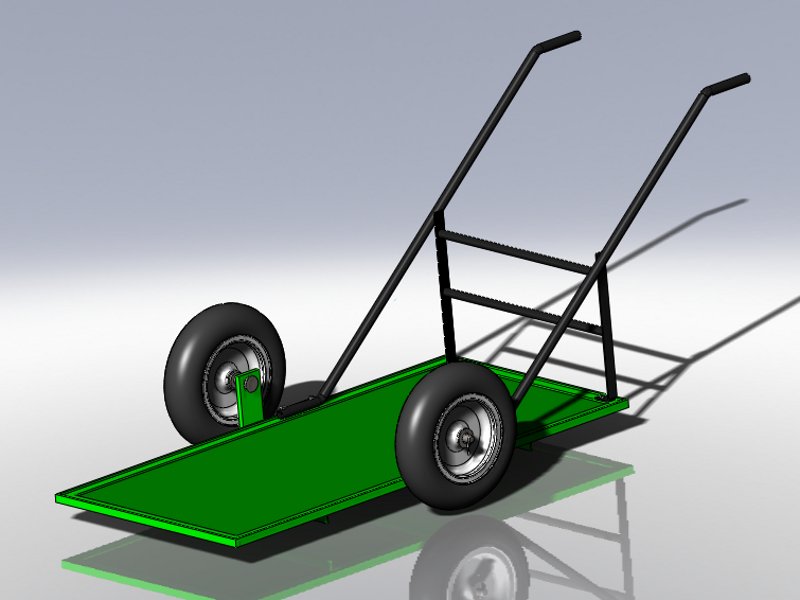
Examination Details:
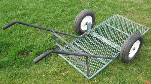
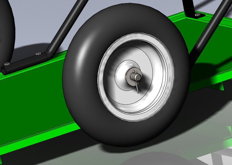
In the 2 examinations for
this class you will be modeling the parts and putting them together in
the assembly of a Low Profile Garden Cart similar to the one in the image
below:
For the first examination
on Tuesday you will model the following parts and then put them into an
assembly named Low Profile Cart:
-
Angle Support (2) (model
before class, see information below)
-
Wheel Support (model
before class, see information below)
-
Base Frame (with 2 configurations,
Bottom Frame and Top Frame)
-
Frame Floor (model before
class per the information given in class)
For the modeling portion of
the examination you will utilize the following design elements including:
-
2 part Configurations on the
Base
Frame
-
Tool Box nuts, washers and bolts
in the assembly
-
2 display states in the assembly,
one green and the other a color plus other attributes of your choice.
Some of the parts will be modeled
before class on Tuesday with information supplied in class or described
below.
The evaluation for the modeling
portion of this exam will consist of the following:
-
Evaluation of your assembly
similar to what we have been doing in class.
-
Include the 2 display states
mentioned above
-
Fully defined
-
Evaluation of a part similar
to what we have been doing in class.
-
Include a part modification
-
A Part Drawing of the Base
Frame (Bottom Frame configuration), to be printed by 7:30pm
on Tuesday.
-
Include all of the elements
shown in class for the Tutor2 drawing and in the templates that
we worked on.
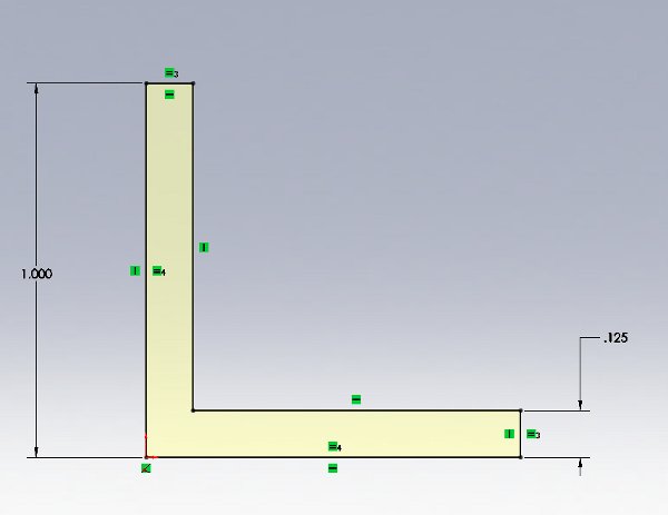
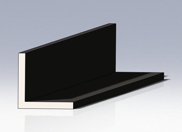
The Angle Support,
model the following part:
-
Material: 1023 Carbon Steel
Sheet (SS)
-
Sketch on the Right Plane in
inches
-
Mid Plane Extrude to 23 inches
-
Hint, draw 2 rectangles and
use the Trim sketch tool
-
Notice the location of the Origin
and Sketch Relations
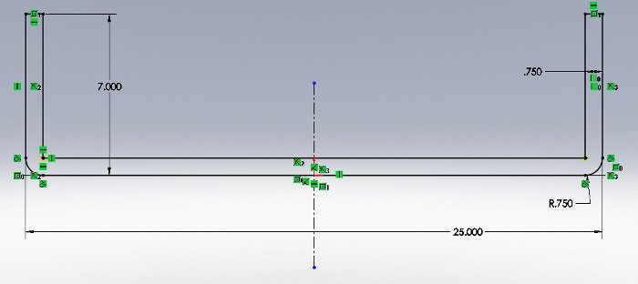
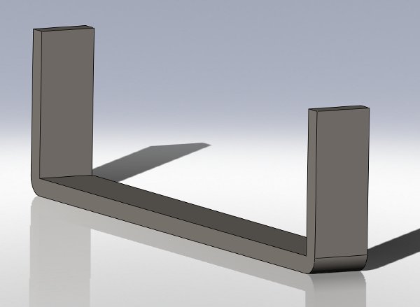
The Wheel Support,
model the following part:
-
Material: 1023 Carbon Steel
Sheet (SS)
-
Sketch on the Front Plane in
inches
-
Mid Plane Extrude to 3 inches
-
Hint, draw a Construction Line
vertical from the Origin then sketch on one side of this line using the
Mirror sketch tool to complete the other side.
-
Notice the location of the Origin
(center on the bottom line) and the various Sketch Relations.
|
- |
|
|
 |
|
-
Week
6:
What
is due on Friday by 5pm:
Image
file of the Candle Stick assembly. (send by email).
Image
file of the Mug (send by email).
Drawing
of your Mug design (in the box (see details below)).
What
is due next Tuesday in class:
Evaluation
of the your Motion Study. |
Those
that missed the evaluation of your exam design assignment (the Low Profile
Cart assembly and the Wheel Support part) during the examination
will have only one additional opportunity for grading on Tuesday, May 4
during class. I will not be taking any points off since extra
credit had been applied to those students who got their assignments done
by the end of the exam.
Nothing
is due on Tuesday. We will go over in class on Tuesday the Candle
Stick and Mug design assignments. On Thursday we will
cover the Threaded Fastener assignment and the Motion Study.
Think
about your Final Project this week. An abstract will be due
iterating your ideas next Tuesday. Run any ideas by me first.
Check previous years' Website for ideas. Check out the Final Project
Abstract link at the Student Resources link. |
Assignments include (due
on Friday by 5pm):
-
Image file of the Candle
Stick assembly using PhotoWorks.
-
High resolution option.
-
Must have a scene and lights.
-
800 x 600 pixels only.
-
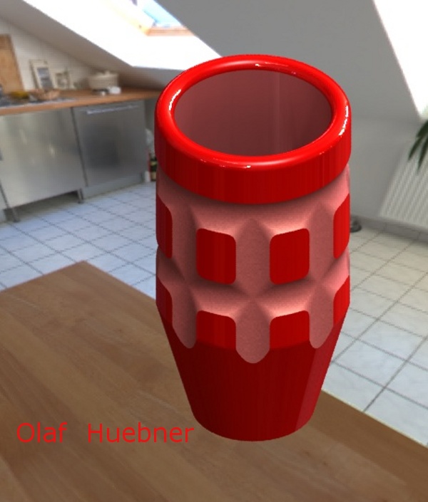
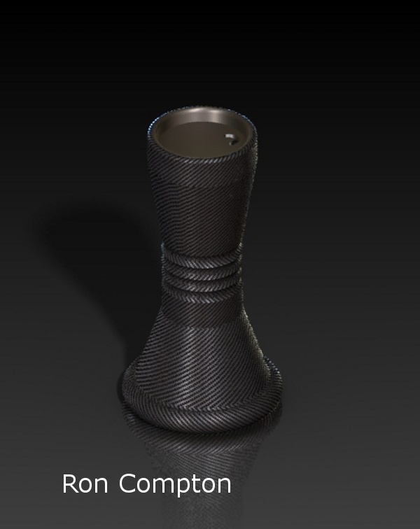
Image file of your Mug
design using PhotoWorks.
-
2 points allocated for creativity
-
Extra credit for extra features
-
High resolution option.
-
Must have a scene and lights.
-
800 x 600 pixels only.
-
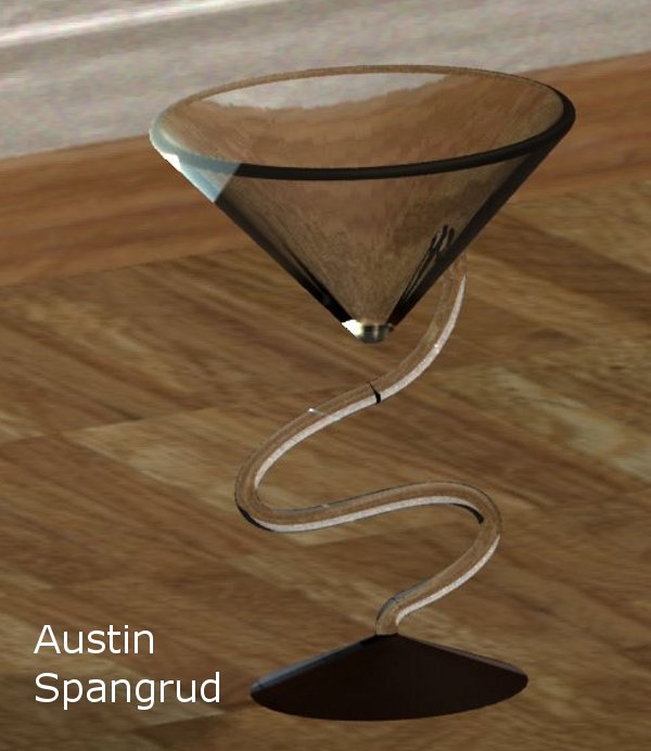
10 points extra credit for a
similar design using the revolved and sweep features (bowls, wine glasses,
cups, trays, top, lamp, etc...)
-
Drawing file of your Mug
design.
-
A sized sheet
-
Display the following views:
-
Front View showing Hidden Lines
Visible HLV
-
Top View with Hidden Lines Removed
HLR
-
Right View with Hidden Lines
Removed HLR
-
Isometric View with Shaded With
Edges SWE
-
Add views titles under each
view
-
Fill the usual values in the
Title Block (as iterated in Project 3) including:
-
your name
-
part name
-
file name
-
company name
-
units of measure
-
dimensioning standard
-
confidentiality statement (filled
in with your company name)
-
Include all appropriate dimensions.
|
- |
|
|
 |
|
-
Week
7:
| What
is due on Tuesday:
Evaluation
of your Motion Study of the Linkage Assembly, instructions
below.
What
is due on Friday:
A drawing
of the Bracket 100 from the Pulley Assembly will be due in
the "box" along with your Final Project Abstract. |
Think
about your Final Project. An Abstract is due on Friday, however,
run any ideas about what you would like to do for your project by me first.
Check previous years' Website for ideas. Check out the Final Project
Abstract link via the Student Resources link below.
We will
start our Threaded Fastener assignment in class on Tuesday and continue
on Thursday. This will be evaluated next Tuesday. |
The Linkage Assembly Motion
Study grading criteria:
-
Create a platform for the air
cylinder
-
Animation, instead of Basic
Motion analysis
-
Must have at least 3 motors.
-
2 rotational motors
-
1 linear motor
-
extra credit for any of the
other motion driving elements
-
No default settings
-
Duration at least 10 seconds
-
Turn on and off motors at different
times
-
Can not have errors
-
Motion has to make sense
-
Create a video
The drawing for the Bracket
100 from the Pulley Assembly shall have the following requirements
along with the usual Title Block elements, View Titles and other features
required on previous drawings:
-
A sized sheet
-
Dual unit dimensions
-
Display the following views:
-
Front, Top and Right Views showing
Hidden Lines Visible, HLV
-
Isometric View with Shaded With
Edges, SWE
-
Front View will be the view
with the face that is coincident to the face of the assembly with the coordinate
system on it, which will be parallel to your screen.
-
Right View shall have centerlines
inserted for the holes in the base with dimensions from these lines.
-
Include an additional view besides
the standard 4 views with a dimension(s).
-
Be certain to fill the usual
values in the Title Block (as iterated in Project 3) including:
-
your name
-
part name
-
file name
-
company name
-
units of measure
-
dimensioning standard
-
confidentiality statement (filled
in with your company name)
Include all appropriate dimensions.
|
- |
|
|
 |
|
-
Week
8:
| What
is due on Tuesday:
Evaluation
of your Threaded Fastener assignment, Pulley Assembly and
the Chisel, Bottle and Screw Driver.
What
is due on Friday:
Two GD&T
drawings. |
We will
cover the procedures of the Spur Gear assignment this week as well
as a couple of projects related to Geometric Dimensioning and Tolerancing
(GD&T). |
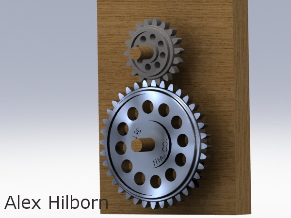
Information on the Spur
Gear assignment can be found at the Student Resources section of the
website.
|
- |
|
|
 |
|
-
Week
9:
What
is happening on Thursday:
Examination
2.
What
is due on Friday:
Two
GD&T drawings. One on the Axle 40 and the other on the
Bracket
100. Details below.
Final
Project preliminary part and assembly drawings. |
|
On Tuesday we will modify
the drawing that we have done for the Bracket 100 part and create a new
drawing for the Axle 40 part (from the Pulley Assembly assignment from
Week 7) related to GD&T. These drawings will be due in the "box" by
Friday. Check out the Student Resources section of the Website for
additional information.
For the Axle 40 part
create a drawing and add the usual dimensions and drawing items plus the
following GD&T items:
-
Datum A on the axis of the axle
-
Datum B on the far left face
of the axle
-
Change the outside dimension
to 20 with a Bilateral Tolerance of no more than 20 but up to 0.10 millimeters
less
-
Add a Feature Control Frame
on this dimension stating a Total Runout tolerance of 0.05 millimeters
referencing Datum A
-
Change the inside dimension
to 16 with a Bilateral Tolerance of no more than 16 but up to 0.10 millimeters
less
-
On the 56 millimeter dimension
add a Feature Control Frame stating parallelism with a tolerance of 0.10
millimeters at the MMC referencing Datum A
-
On the 86 millimeter dimension
add a Feature Control Frame stating perdendicularity with a tolerance of
0.10 millimeters at the MMC referencing Datum B
For the Bracket 100
part
drawing modify the drawing and add the following GD&T items:
-
Datum A on the bottom face of
the part
-
Datum B on the axis of the axle
hole
-
Datum C on the outside vertical
face of the triangular axle mount.
-
Modify the dimension on the
hole for the axle to have a Bilateral Tolerance of up to 0.05 millimeters
more but no less than 16 millimeters
-
Add a Feature Control Frame
with 2 lines on this dimension stating that the hole needs to be parallel
to Datum A with a tolerance of 0.05 millimeters at the MMC and on the second
line, perpendicularity to Datum B and Datum C with a tolerance of 0.05
millimeters at the MMC.
-
Modify the dimensions on the
10 millimeter mounting holes adding a Symmetric Tolerance of plus or minus
0.10 millimeters.
-
Add a Feature Control Frame
on this dimension stating that the position of the mounting holes have
a tolerance of 0.10 millimeters at the LMC referencing Datum A and Datum
C
On Thursday we will have our
Examination 2.
Examination Details:
Information on various parts
needed for the Low Profile Cart assembly follow below:
The parts include the following:
Floor Frame (Exam 1)
Base Frame, Top Frame Configuration
(Exam 1)
Base Frame, Bottom Frame
Configuration (Exam 1)
Angle Support (Exam 1)
Wheel Support (Exam 1)
Wheel (see below)
Tire (see below)
Wheel-Tire sub-assembly
(see below)
Handlebar (see below)
Handlebar Support Assembly
(given, see below)
Handle (see below)
Axle with Loft Features
(part of Exam 2)
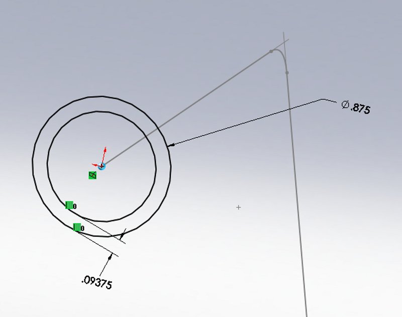
Wheel, model the
following part:
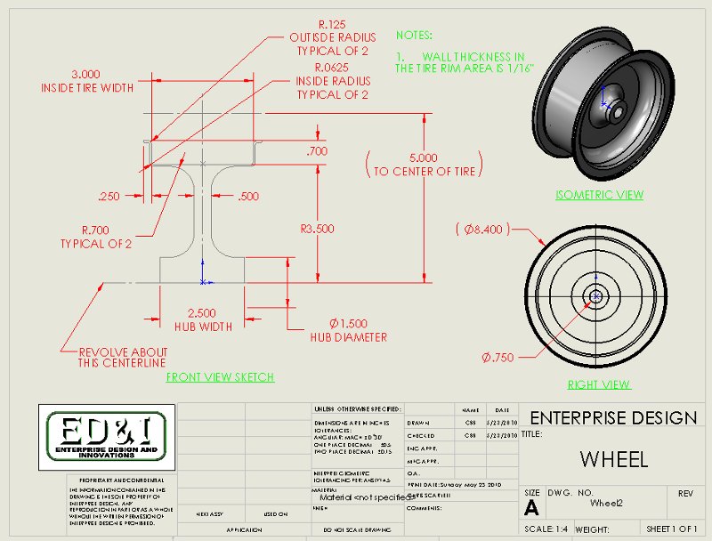
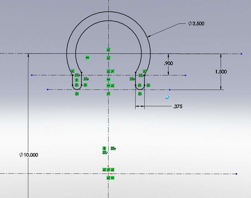
Tire, model the
following part:
-
Material: Rubber
-
Sketch on the Front Plane in
inches
-
Hint, Tire thickness is 0.375"
-
Sketch the reference geometry
first, the four centerlines with dimensions
-
Sketch the outside arc first,
the center of the arc is vertical of the Origin and on the 10 inch diameter
centerline
-
Use the mirror sketch entity
for the tire rim portion
-
Revolve Boss/Base
-
Notice the location of the Origin,
same location as in the Wheel (this is important for the sub-assembly)
-
Add treads for extra credit
-
We will cover this model
in class on Tuesday

Wheel-Tire, assemble
the following assembly:
-
Create an assembly named Wheel-Tire
-
Insert both parts "fixed" to
the Origin.

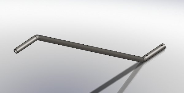
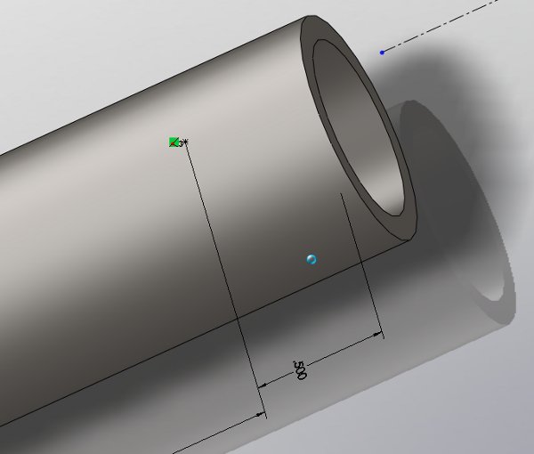
Handlebar, model
the following part:
-
Material: 1023 Carbon Steel
Sheet (SS)
-
Swept Boss/Base
-
Sketch the path on the Right
Plane
-
Insert a reference plane at
the end of the path and sketch the profile as shown below
-
The wall thickness is 3/32"
-
Insert a reference plane so
that it is parallel to the Top Plane and tangent to the front end of the
Handlebar for the Hole Wizard.
-
Use the Hole Wizard on the recently
inserted plane using the same settings and distance as it is on the Base
Frame
-
The first Hole Wizard hole is
1/2" from the front end of the Handlebar

Handlebar Support Assembly,
download the following assembly and parts:
Download

Handle, design
your own part
-
Material: of your choice
-
Must contain Loft Features
-
Must fit over the handlebar
More information later
|
- |
|
|
 |
|
-
Week
10:
| Work
on your Final Project parts assemblies and drawings this week. Ample
help will be available.
Final
Project part and assembly drawings, second round, are due in the "box"
on Friday. |
|
Hand in your Part and Assembly
Drawings by Friday in the Box.
-
These will be your final drawings,
worth 15% (30 points) of your Final Project grade and should include the
following:
-
Sheet size of your choice.
-
All of the elements that have
been required throughout the quarter.
-
Assembly drawings should have
basic dimensions only
|
- |
|
|
 |
|
-
Hand in your Part and Assembly
Drawings after the Final project Presentations today in the Box.
-
These will be your final drawings,
worth 15% (30 points) of your Final Project grade and should include the
following:
-
Sheet size of your choice.
-
All of the elements that have
been required throughout the quarter.
Assembly drawings should
have basic dimensions only
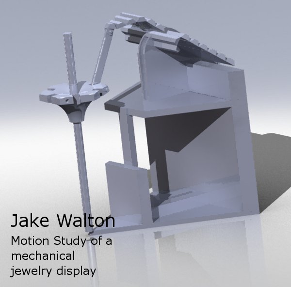
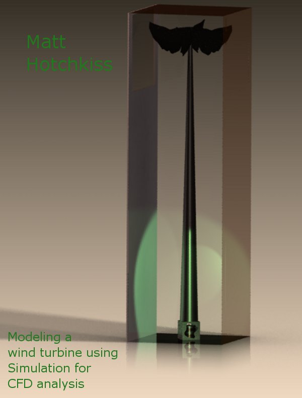
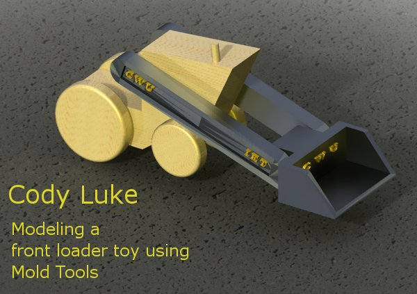
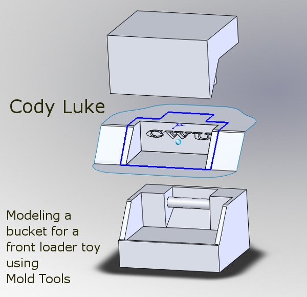
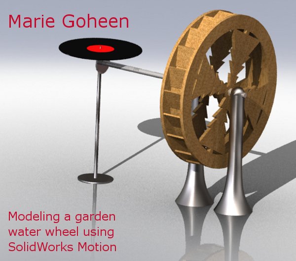
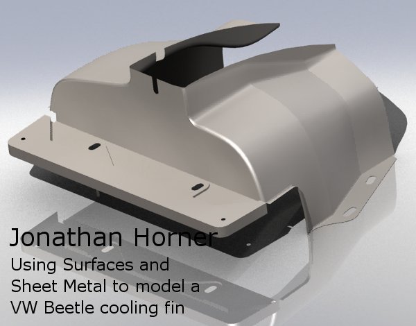
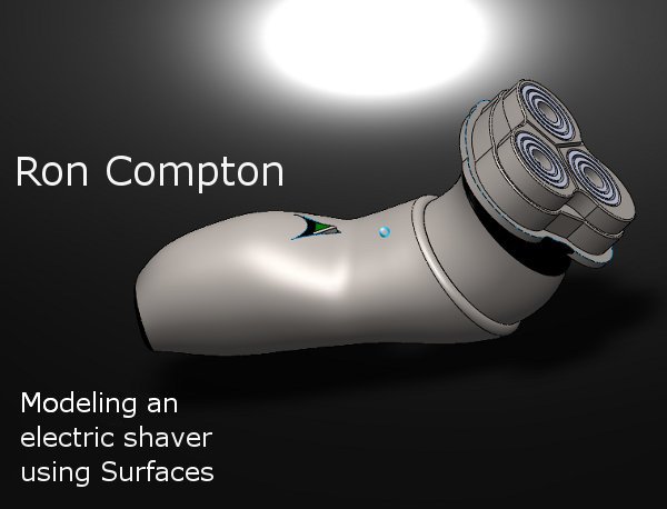
Below are some images and videos
of your completed projects:
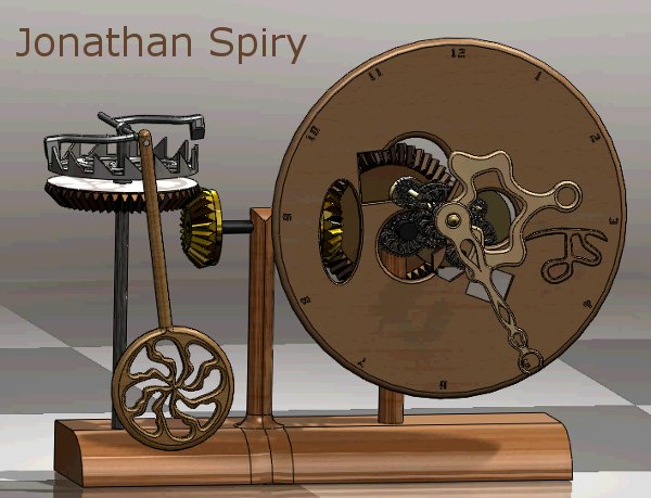
click on the image above
for a video
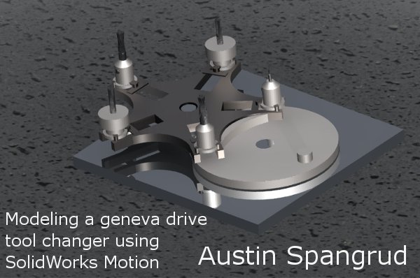
click on the image above
for a video


click on the image above
for a video


click on the image above
for a video
-
-
|