|
|
- |
|
|
 |
 |
-
| Week
1:
Read
before next Tuesday's class the Introduction and Lessons 1 and 2 of the
text book, Residential Design Using AutoCAD 2011.
| What
is due: Come to class on Tuesday of next week with a penciled sketch
of a floor plan so that you can get started on your Final Project.
Include rough dimensions. We will work on this floor plan in CAD
over the next week or so. |
|
|
- |
|
|
 |
|
-
Week
2:
| What
is due: Sketched floor plan, drafted floor plan, example 2-2 on page
2-20 and your drawing template. |
In class
we will begin using AutoCAD, create an architectural template file and
start our floor plans. |
For Tuesday we will jump
into AutoCAD and become familiar with the basics. We will also create
our template file complete with a title block.
Begin to draft your floor
plan and complete exercise 2-2 before class on Thursday. On Thursday
we will continue and finish Lesson 2 as a class exercise and modify our
template file to include a Title Block. We will then take our updated
template file with the title block and incorporate it with our preliminary
floor plan and exercise 2-2. For the Floor Plan draw lines representing
the exterior and interior walls. You do not have to dimension or
scale the drawing.
Over the weekend, start drafting
the details in Lesson 3 which will be due next Friday.
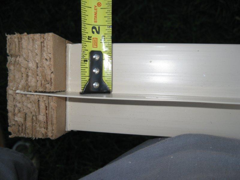
Steps on Creating Your Title
Block:
-
Create 3 new layers, "Title
Block Border" make this yellow, Title Block WHT, make this white and Title
Block GRN and make this green.
-
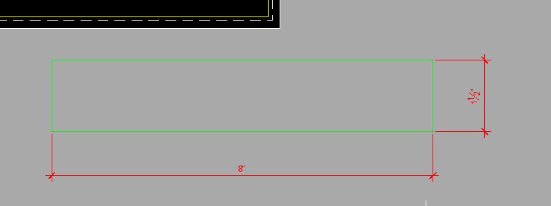
On the Title Block Border layer,
in Paper Space (Layout) create a rectangle at the start point of 5/64 tab
5/64 and make it 10.5 tab 8.
-
This creates a yellow rectangle
10.5 inches long by 8 inches high offset 5/64ths of an inch from the origin
or the lower right hand corner of the paper margin, see below.


-
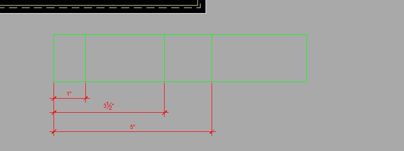
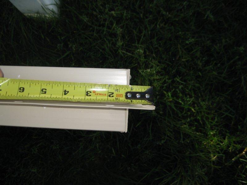
On the Title Block GRN layer,
off to the side of the paper on your Layout draw another rectangle for
your Title Block 8 inches long by 1.5 inches high.
-
Also on the Title Block GRN
layer draw vertical lines at the distances shown below.
-
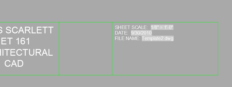
On the Title Block WHT layer
create text (Choose the Multiline Text in the Annotation Panel of the Ribbon)
with the information shown below (use your name). The text should
be justified to Top Center, 3/16" high and change to "No" from "Yes" in
the row labeled Match orientation to layout.

-
Repeat the step above using
the information shown below. The text height will be 3/32".
-
Take your Title Block and rotate
it
90 degrees as shown.
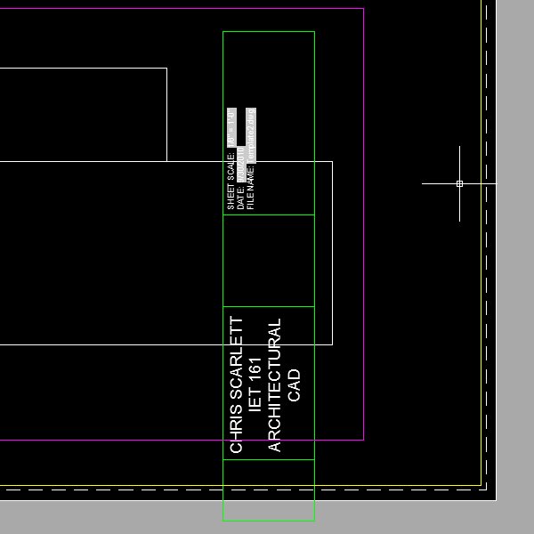
-
Move your Title Block into the
corner defined by your border.

-
Save your template file perhaps
as Template2.dwg
|
- |
|
|
 |
|
-
Week
3:
| What
is due: Hand in the Architectural Objects (Plan Details) from Lesson 3. |
This
assignment will be sent to me via email by Friday at 5pm.
A printed
version of a plan detail, of your choosing, will be handed in, with the
current Title Block, via the "box". |
For Thursday continue drafting
the Architectural Objects (Plan Details) in Lesson 3 using the following
guidelines.
Draft all of the objects
in Lesson 3 into one AutoCAD file. Do all of them excluding the window
elevations (we will do those later) and the handicap symbol. The
intent here is to create a large file of architectural objects or details
that can be copied into our floor plans. We will create AutoCAD blocks
of these objects and ultimately dynamic blocks.
Design a plan detail of your
choosing with at least 15 drawing entities. You will get extra credit
for more detail. This design may include any thing that could be
used in a floor plan. Your work has to be unique!
Procedure for drafting Architectural
Objects:
-
Open your template file and
resave it in the Week 3 folder in your storage medium named something similar
to "Architectural-Objects.dwg"
-
Draft everything in Model Space
-
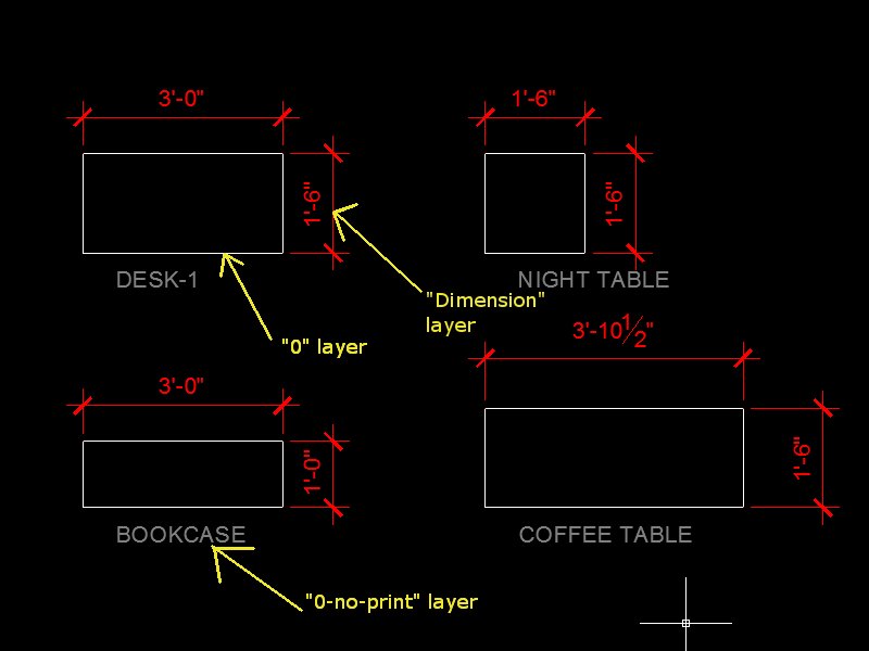
Draft the objects on the "0"
layer (more about the special properties of the "0" layer in class)
-
Draft the "Bookcase" starting
at the origin (0,0) as the textbook suggests
-
Draft the other objects close
to the "Bookcase" but at no particular distance from each other (don't
crowd your objects though)
-
Create a layer named "0-no-print",
color it dark gray #8, designate it not to print.
-
Include annotation describing
each object within, underneath or close by that object on the "0-no-print"
layer. See the image below.
-
Dimension your objects and "Fit"
the dimensions to a scale factor of 24.
-
The dimensions will have to
be deleted or told not to print before inserting them into you floor plans.
More on this later.
|
- |
|
|
 |
|
-
Week
4:
| What
is due: Lesson 4 Floor Plan, updated Floor Plan for your Final Project,
updated Architectural Objects with Blocks. |
Follow
the instructions below when going through Lesson 4. Hand in, by Friday's
deadline, your Lesson 4 Floor Plans for the basement, first and second
floors with dimensions (doors and windows are not required) with your updated
Template file and Title Block on Architectural B paper in the box.
Also
hand in a preliminary Final Project floor plan emulating the procedures
in Lesson 4 with your updated Template file and Title Block on Architectural
B paper in the box.
Update
your Architectural Objects and send those via email like last week.
Draft the doors and make blocks out of all of the objects. |
Start Lesson 4 in the text
book with the following exceptions and modifications to what is discussed
in the book.
-
Create one drawing with all
three floor plans, not the three different drawings as suggested in the
book. Just like with our Architectural Objects from Week 3 we will
create various blocks in one drawing.
-
Ignore the discussion on setting
the drawing limits.
-
Create three new layers in lieu
of the one layer as suggested by the book.
-
A-Wall-B, color white
-
A-Wall-1, color yellow (for
now) change it back to white before printing
-
A-Wall-2, color green (for now)
change it back to white before printing
-
Draft the basement floor first
in the location discussed in the book using the "A-Wall-B" layer.
-
Copy the basement floor plan
up 1000 units (inches) and use this as a template for the first floor floor
plan (rather than starting from scratch again).
-
Do the same for the second floor.
Regarding the Architectural
Objects:
-
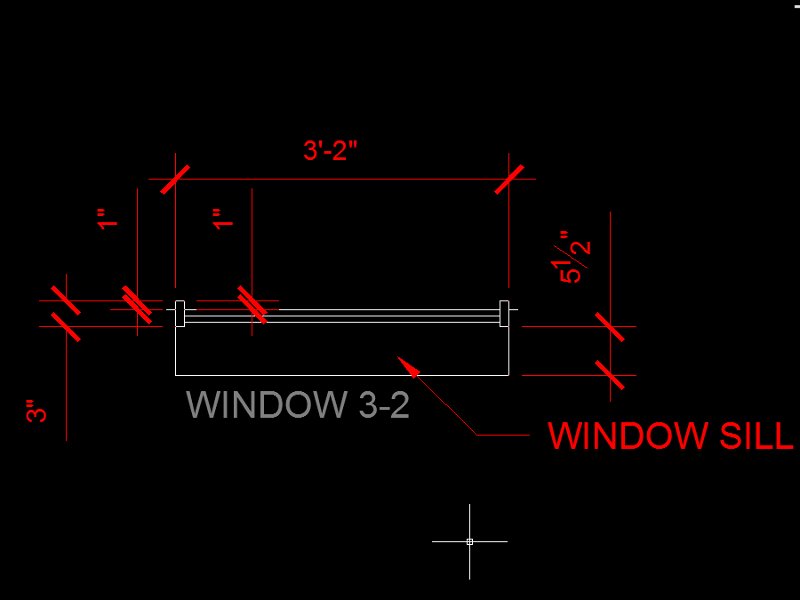
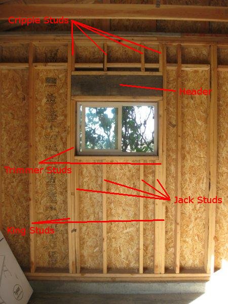
When drafting windows:
-
Use the full window size width
as the book suggests. This will make it easier.
-
Create only one window layer
not two, but draft the window lines on the "0" layer before making a block
just like the other objects.
-
For an example of a window object
that would be fit for a floor plan see the image below. Do not label
the window sill:
Below are some images of
a remodel showing some floor plan elements that may be useful in understanding
your work this week:
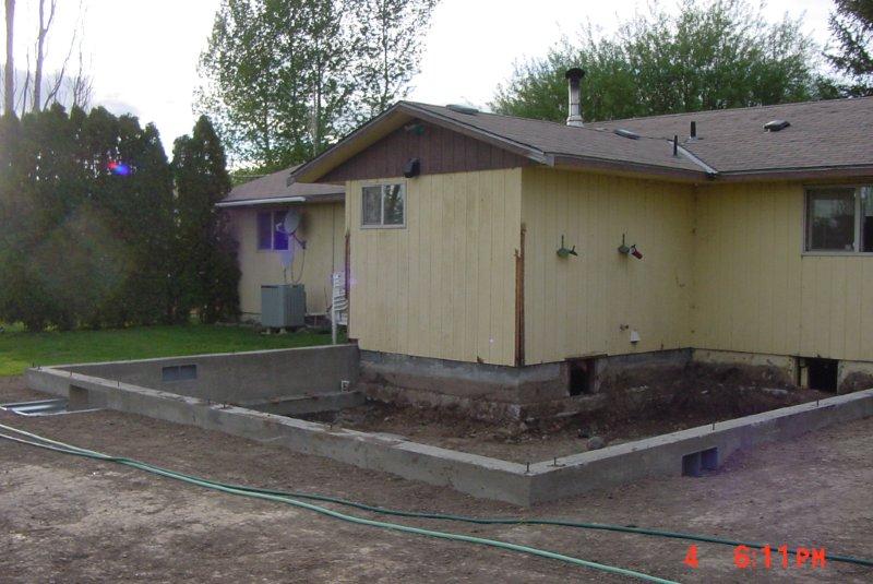
The image below shows a new
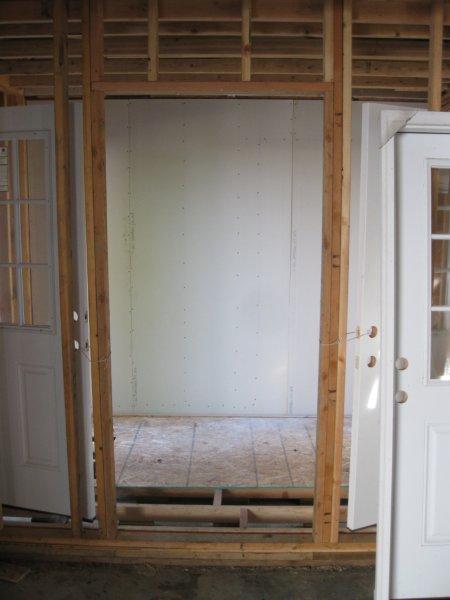
stem wall foundation on an existing house adding a bedroom addition.

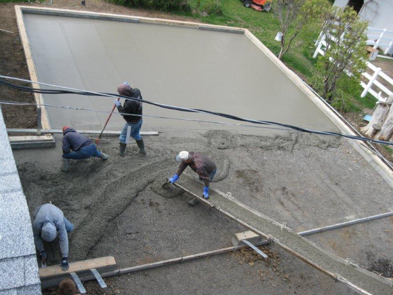
The image below shows, two
days later, the new sub-floor on top of the new stem wall foundation.
It is this surface, the top of this floor, that the floor plan is designed
from. Notice that the exterior edge of the sub-floor is lined with
the edge of the stem wall foundation.

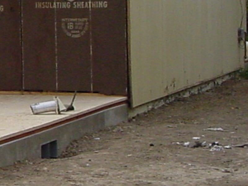
The image below shows a close-up
of the previous image where the new addition meets the existing house.
Notice how the siding covers the edge of the sub-floor and extends about
2 inches below the top of the stem wall foundation.
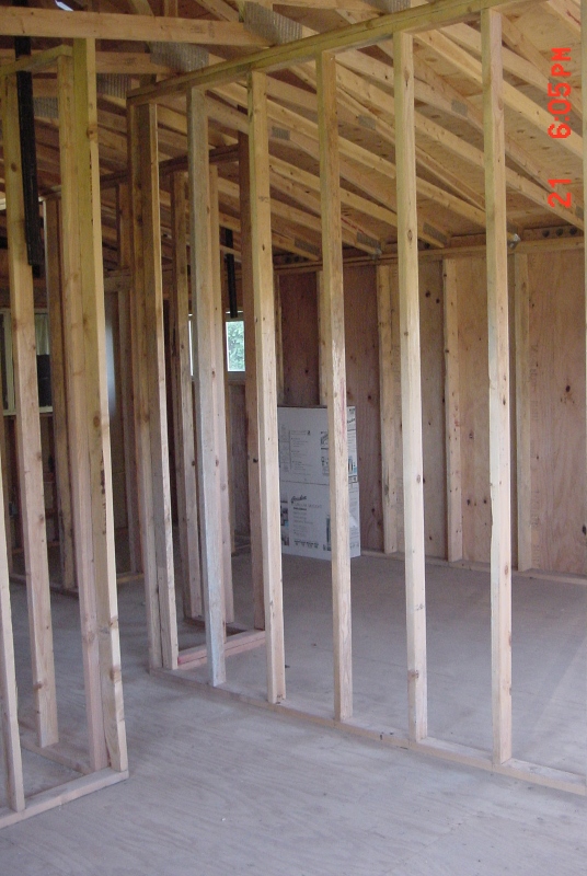
The image below shows the
inside of this space showing the interior walls (2x4 construction) and
exterior walls with sheathing (2x6 construction).
The images that follow show
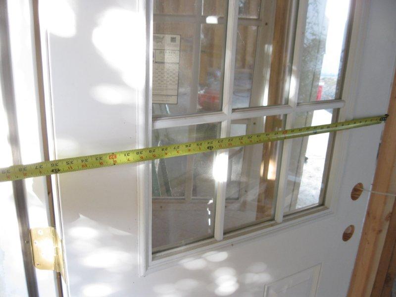
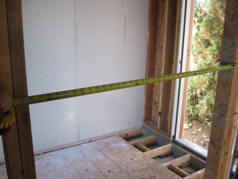
dimensions associated with a standard 36" door installation. The
image below is a 36" exterior door (6-1/2" exterior wall thickness).
The actual door size is 35-7/8".
The actual door size is 35-7/8"
(close up).
The exterior dimension size
is 40" including the exterior trim (brick mold).

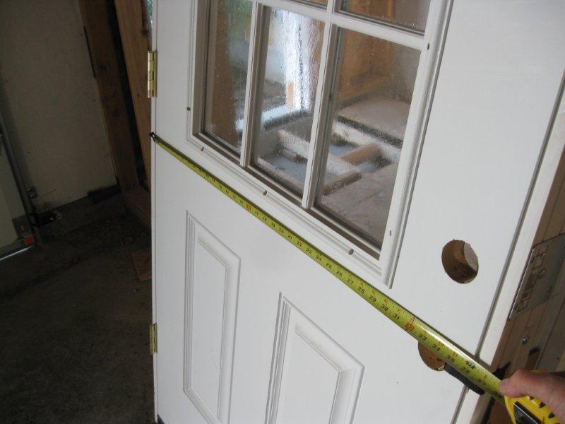
The actual opening of the
door, inside clearance is 36". This measurement determines the door
size.
The actual opening of the
door, inside clearance is 36" (close up).

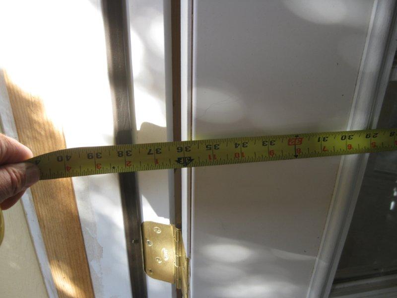
The door frame on the interior
of this door is 37-1/2".
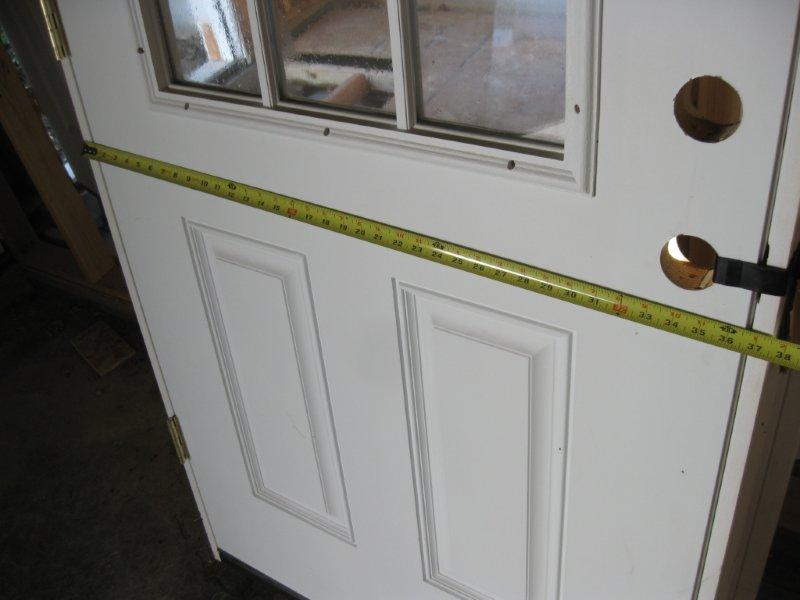
The door frame on the interior
of this door is 37-1/2" (close up).
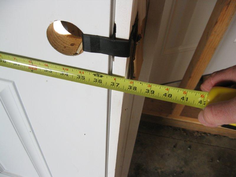
The framed door opening.
The framed door opening (rough
opening) height (about 81-3/4").
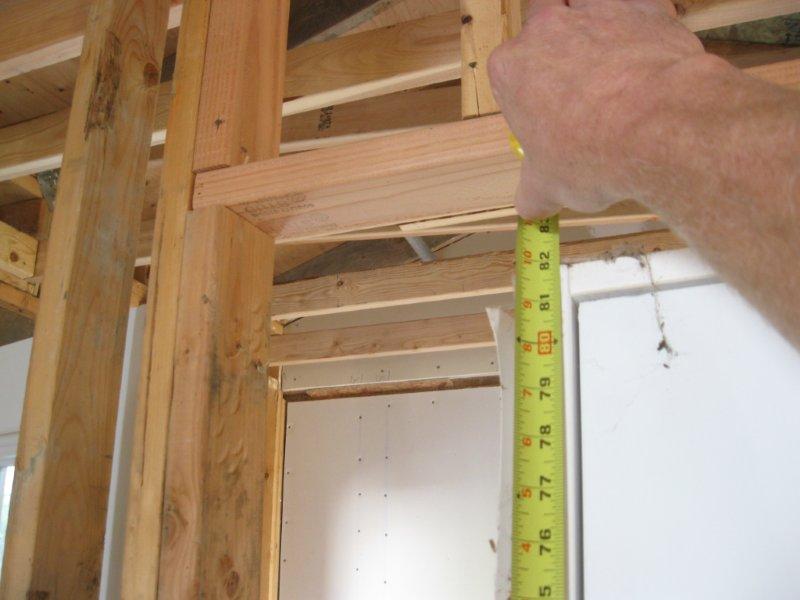
The framed door opening (rough
opening) width.
The framed door opening (rough
opening) width at 38-1/4" (close up) (usually 38"). This gives us
about a 3/8" on each side of the door for adjustments, using shims, during
installation.

The images that follow show
dimensions associated with a standard 3' x 2' window installation. The
image below shows a framed window opening and window on the interior of
a garage for 3' x 2' window.
The framed window opening
(rough opening) for 3' x 2' window (close up). This is one of the
measurements that determine the window size.
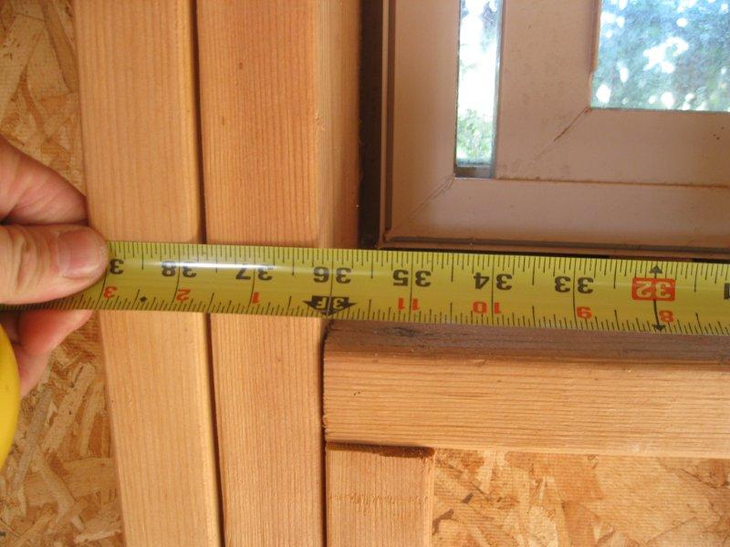
The framed window opening
(rough opening) for 3' x 2' window (close up). This is one of the
measurements that determine the window size.

An uninstalled 3' x 2' window.
The window measures about a 1/2" less on each side referencing the window
size. This gives us about a quarter inch on all sides of the
window for adjustments, using shims, during installation.

Window and frame is about
3" thick.

The nailing flange is positioned
about 1" back from the exterior edge of the window.
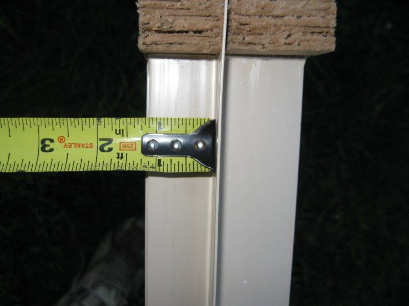
The nailing flange is about
1" long.
A finished window from the
exterior excluding caulking and paint, notice the nailing flange is covered
by the window trim.

A finished window on the
interior with a window sill.
|
- |
|
|
 |
|
-
Week
5:
| What
is due: Updated Architectural Objects with Lesson 4's doors and windows. |
Update
your Architectural Objects and send those via email like you have done
for the past 2 weeks. Draft the doors and windows from Lesson 4
(closet door, pocket door etc.) and make blocks out of all of the objects
with appropriate basepoints. |
There will be an abbreviated
class session Thursday. I need to leave for a meeting at about 5pm.
Follow the book for Lesson
4 with the following exceptions:
Architectural Objects
-
Draft swing doors with a frame
as it was demonstrated in class.
-
Draft the other doors from Lesson
4 similar to the book or as demonstrated in class.
-
Draft windows as shown in the
Week 3 section above in lieu of instructions on page 4-36
-
Draft objects on the "0" layer
with dimensions and labels as demonstrated in class
-
Make Blocks out of all objects
-
Change the name of the dimension
layer to "Dimension-Block" before inserting blocks into your floor plans.
Lesson 4, the Floor Plans
-
Create the following layers
-
"A-Doors", color green, in lieu
of instructions on page 4-29
-
Insert your door blocks on this
layer.
-
"A-Windows", color green, in
lieu of instructions on page 4-37
-
Insert your window blocks on
this layer.
-
"Dimension-Door" dimension your
door placements with this layer.
-
"Dimension-Window" dimension
your window placements with this layer.
-
Change the name of your dimension
layer to "Dimension-A"
-
With the above dimension changes
you can turn off various dimension layers while inserting doors and windows
to reduce the clutter. When printing you need to turn back on all
of the dimension layers except for the "Dimension-Block" layer organize
all of your dimensions.
-
Change the color of the A-Wall-B,
A-Wall-1 and A-Wall-2 to white before printing.
-
Follow the changes in the section
on dimensions starting on page 4-45.
-
In the bottom panel of page
4-47, "Text placement", do not choose the "Over dimension line, without
leader" option, choose the default setting instead "Beside the dimension
line".
-
Do not follow the section on
"Annotation Scaling" starting at number 11 through 14 starting on the bottom
of page 4-48.
|
- |
|
|
 |
|
-
Week
6:
| Examination
1 on Tuesday.
What
is due on Tuesday: Lesson 4 Floor Plans with Task 4-2 (3 drawings), Floor
Plan for your Final Project (1 drawing). Hand in 4 drawings total.
What
is due on Friday: The Exterior Door Design Project. |
Hand
in, by Tuesday before the exam, your Lesson 4 Floor Plans for the basement,
first and second floors complete with doors and windows and dimensions
with your updated Template file and Title Block on Architectural B paper
in the box.
Also
hand in, by Tuesday before the exam, a preliminary Final Project floor
plan with doors and windows emulating the procedures in Lesson 4 with your
updated Template file and Title Block on Architectural B paper in the box.
Also
hand in, by Tuesday before the exam, Task 4-2 at the end of Lesson 4 and
incorporate that into your floor plans.
For extra
credit you may incorporate Task 4-3 or any of the other Tasks in the back
of the lesson.
On Thursday
I will be grading your door image for a simple 10 points. We will
then be working on the door design for part of the class. For Friday
hand in your door design project on your A sized drawing template.
On one side of the sheet will be your drafted door with dimensions (15
at least) and on the other an artistic rendering using hatching and colors
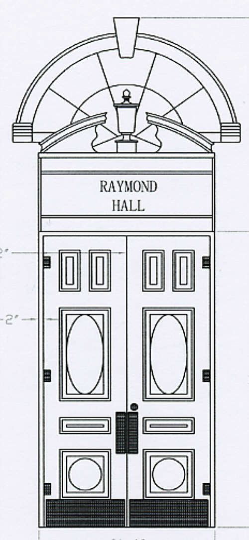
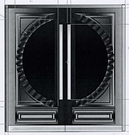
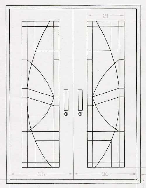
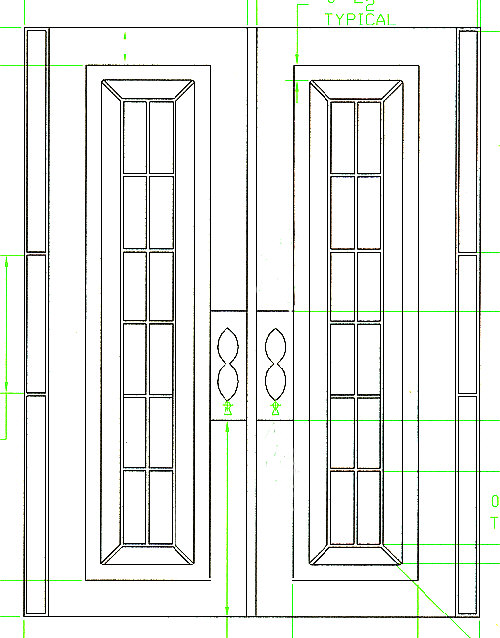
if desired. Print out in color. |
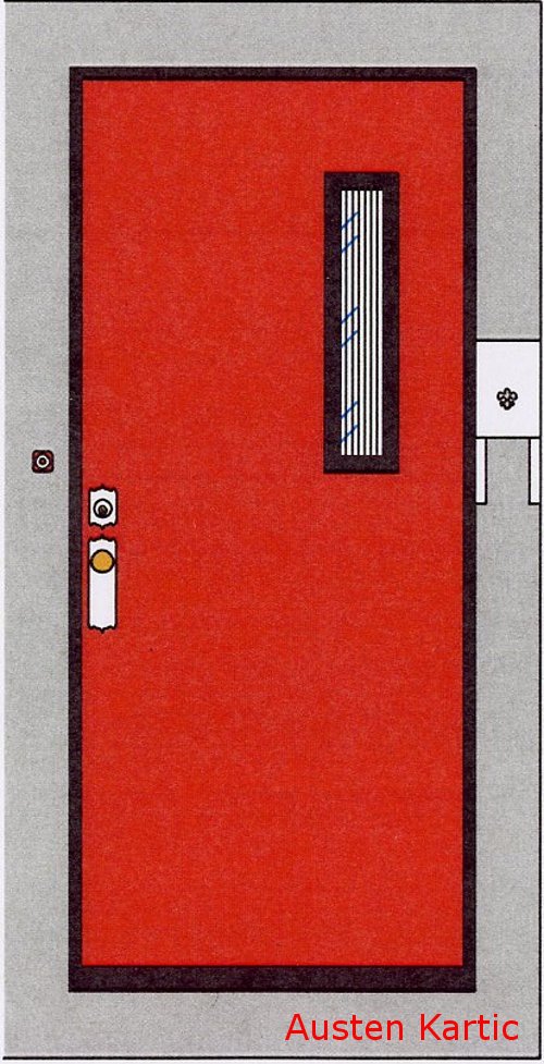
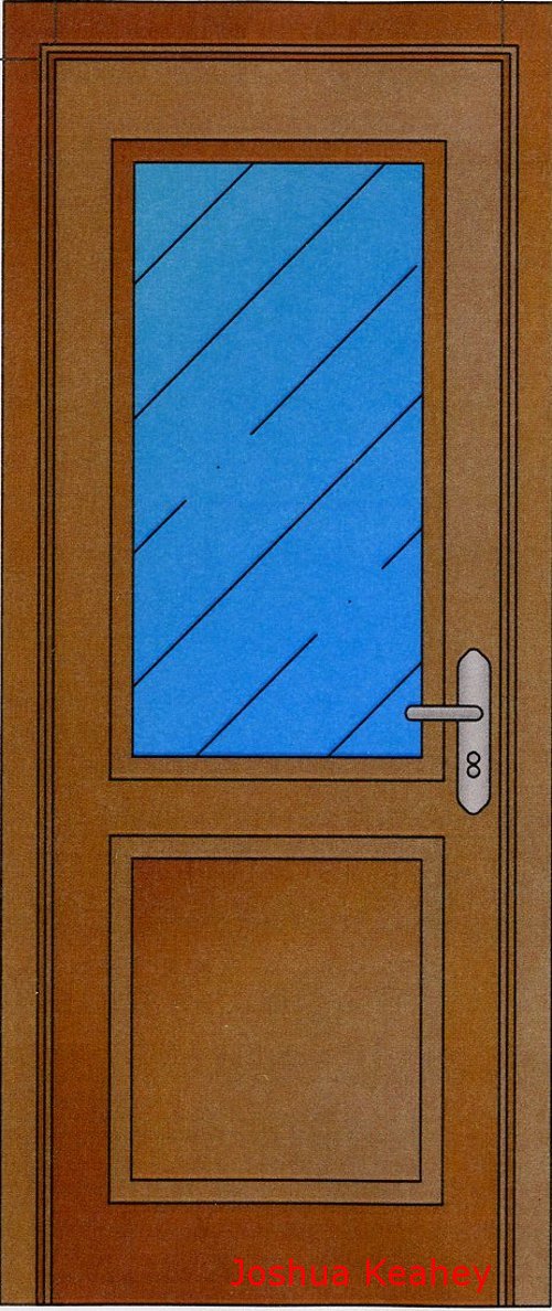
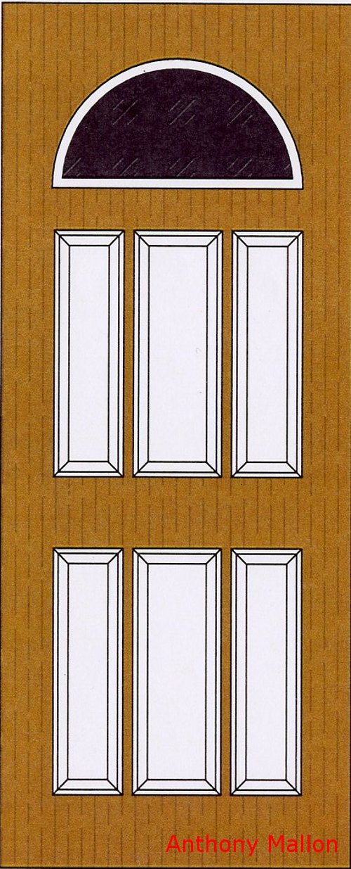
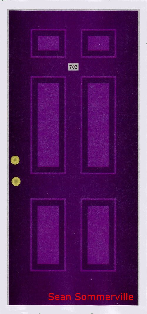
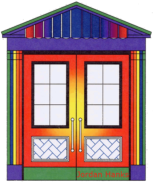
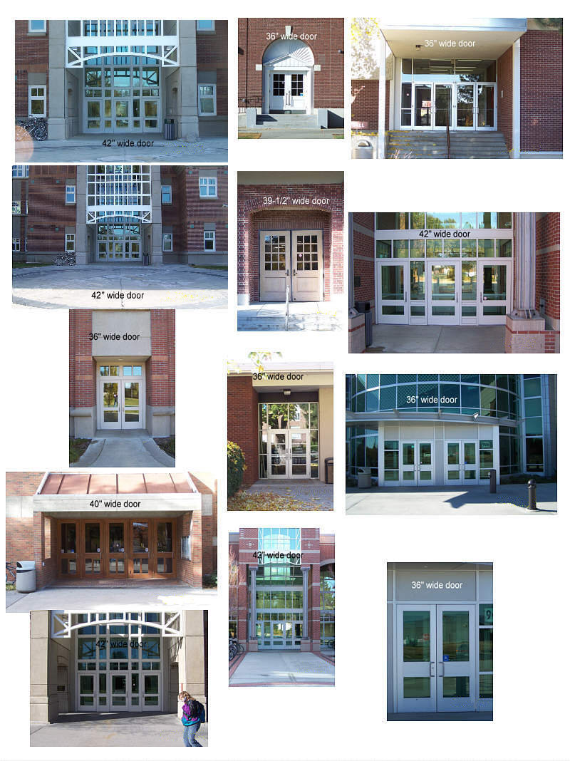
For Thursday find an exterior
door on campus or around town that you think is an attractive design that
you would like to emulate, take a digital image of it and measure the width
of the door opening (door size). Bring the image and the measurement
to class. Some door examples around campus are included in the image
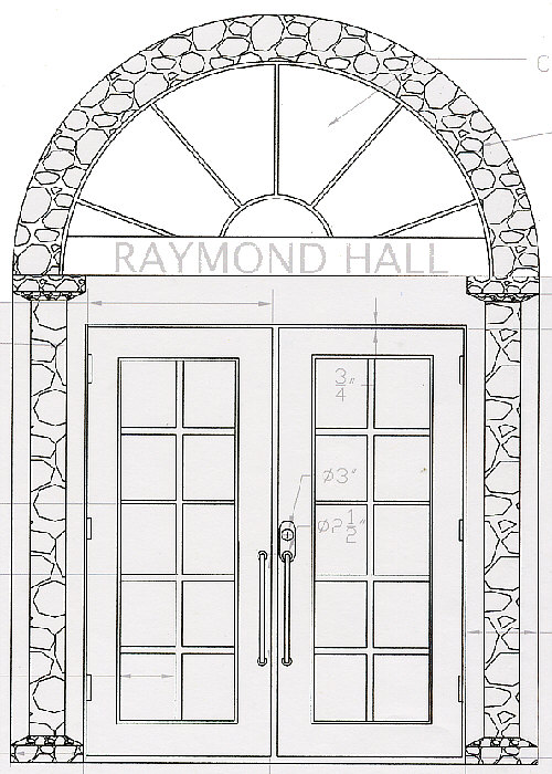
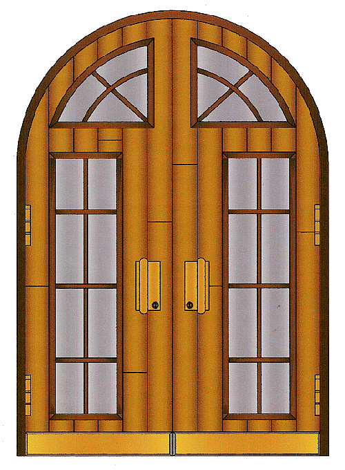
below. The door examples that follow that image below are what I
consider to be great designs from previous students. A common method
used for detailing is the hatch commend.


|
- |
|
|
 |
|
-
Week
7:
| Continue
Lesson 5
What
is due by Friday: Send to me, via email, your updated Architectural Objects
including the window and door elevations from Lesson 5. |
|
Follow the book for Lesson
5 with the following exceptions:
Architectural Objects
-
Window Elevation Blocks.
Draft all of the window elevations from Lesson 5 in this file in a similar
manner as we have done so far.
-
Make Blocks out of all objects
-
Name your windows based on their
size using the width first then the height in feet units followed by inches
separated by a dash. For example the first window is about 3 foot
2 inches in width and 4 foot 10 inches tall. This could be named
"Window 3-2 4-10".
-
Window 1 "Window 3-2 4-10"
-
Window 2 "Window 6-8 4-10"
-
Window 3 "Window 6-8 6-6"
-
Window 3 "Window 3-2 6-6"
-
Door Elevation Blocks.
Draft all of the door elevations from Lesson 5 in this file in a similar
manner as we have done so far.
-
Suggested door names using the
door width considering that the door heights are about 81 inches:
Lesson 5, Elevations, create
a new AutoCAD file. Use your template or your floor plan file, save
as your elevation file before drafting.
-
Create the following layers
-
"A-Elevations", color white
(in lieu of instructions on page 5-1)
-
"A-Elev-Windows", color green
(page 5-21)
-
Insert your window blocks on
this layer.
-
A-Elev-Doors", color green (page
5-29)
-
Insert your door blocks on this
layer.
-
"Dimension-E, color red, dimension
your elevations on this layer
-
"A-Elev-Railing", choose a light
color but not yellow (page 5-41)
-
"A-Elev-Roof", choose a light
color but not yellow (page 5-44)
-
"A-Elev-Siding", choose a light
color but not yellow (page 5-47)
-
"A-Elev-Chimney", choose a light
color but not yellow (page 5-46)
-
"A-Elev-Foundation", choose
a light color but not yellow (page 5-52) This layer is for Tasks 5-1 and
5-4
|
- |
|
|
 |
|
-
Week
8:
| What
is due by Friday: Print and deposit into the box the elevations
as described in the book with the modifications as listed below incorporating
Task 5-1 and Task 5-4. Design and incorporate into your Title Block
a logo for you or your company as well as the Title Block modifications
listed below. |
Design
a logo, see details below. |
Lesson 5, Task 5-4, foundation
lines display information.
The information in the book
is not as correct or as clear as it could be when it comes to displaying
foundation lines for the Lesson 5 elevations. The following information
are procedures and modifications to the book.
-
All stem wall or basement wall
vertical foundation lines are collinear to the lines representing the exterior
walls of the house so start with these and extend them down per the book.
-
The image for the west elevation
is OK.
-
The image for the south elevation
should be modified so that:
-
The garage foundation will have
a footing, stem wall and a slab in lieu of the implied dungeon in the book.
-
The footing dimensions are the
same as described on page 6-4
-
The stem wall is 24 inches tall
-
The slab is 4 inches thick
-
Show foundation lines for the
chimney
-
Show a footing for the columns
in lieu of what is in the book
-
20" wide by 12" thick (similar
to the book footings).
-
The image for the east and north
elevations will have the same modifications as a described above.
Test question: When drafting
a dashed line in this class what does it represent?
Extra credit for this week
only: Look at the first floor, floor plan and notice how the front door
is offset from the front of the house. Show this on your elevations.
Design a logo for your title
block. Choose a name and style that fits your career ambitions or
personality. Consider some design ideas that you can find on the
web. Below are some images of some CAD files of logos from some companies
that we have worked with in the past. The logo examples that
follow the company logos are what I consider to be good designs from previous
students.
Title block changes will
be as follows:
-
Add a logo and vertical text
for your company including a mailing address and phone number in a box
on the top (right) of your title block. The logo box is 2-1/2"
by 1-1/2". Your logo must be unique, done in CAD (no images) and
it must fit in the space allocated in your title block.
-
In the title section, where
it now says something similar to "YOUR NAME, ARCHITECTURAL CAD IET161,
FIRST FLOOR PLAN" change this to read something similar to the following,
with your unique information, (in descending order of significance, or
from the most general in nature to the more specific) "PROJECT NAME (such
as EAGLE RESIDENCE) followed by what kind of construction it is (such as
"NEW CONSTRUCTION", "REMODEL", "NEW HOME") followed by the sheet name (such
as BASEMENT FLOOR PLAN). Make certain that your name is in the title
before the word residence. Center and center justify this text.
-
In the bottom box include horizontal
text stating "SHEET A# OF #" where the # symbol corresponds to numbers,
for example, if you have 12 sheets and the basement floor plan is sheet
3 then it would read "SHEET A3 OF 12".
Some logo examples follow
below:


|
- |
|
|
 |
|
-
Week
9:
| Plan
on correcting your elevation assignments from week 8. The images
below may help you in understanding footings, stem walls and slabs.
What
is due: Corrected Week 8 assignments including the elevations, title
block and Task 5-1 and Task 5-4. Section from Lesson
6. |
On Tuesday
we will go over the elevation assignments from Week 8.
On Thursday
we will start Lesson 6 on Sections. |
Correct the assignments from
last week for up to 90% (18 points). To get this credit include the
markup as well as the corrected assignment.
Information on the section
assignment will be covered on Thursday. Download the section arrow
for
your floor plan at the following link:
section
arrow symbol
The arrow comes in at a scale
factor of 48 so you'll have to scale it for your Final Project floor plan
scales.
Include all of your designs
such as your floor plans, elevations, sections and site plans on one drawing.
Name this drawing similar to a name like Sheet-Set. When you compile
your Final Project you should follow a similar format.
Below are some images of
some of the details that we went over in class.
Below are some images of
footings, stem walls and a slab for a garage (that was built last spring
by the CMGT 245 class). You may find this helpful when correcting
your elevation assignments from week 8.
Below is an image of a footing
and stem wall for a crawl space (May 2004).
Below is an image of a footing
and stem wall for a garage project last spring, notice the how the footing
sticks out both inside and outside the stem wall (4"). The footing
is 16" wide, 8" tall and the stem wall is 8" wide and 24" tall. The
back hoe is leveling the grade and back filling the exterior portions of
the wall. With aggregate (seen below at the door entrance) and 5/8"
crushed rock added later, the back hoe will fill in and level the interior
prior to the pouring of the slab. Chalk lines have been drawn on
the interior stem wall to guide the leveling (May 3, 2010).

Below is an image showing
the compacted fill up to about 6" below the top of the stem wall.
The water is to keep the fill wet which helps the concrete to cure slower
and thus stronger (May 3, 2010).

Slab pour day, notice the
aluminum board on the gravel. This is used as a thickness guide for
the pour (May 6, 2010).

Slab pour day, moving from
the back to the front (May 6, 2010).

Slab pour day, pouring, spreading
and leveling (May 6, 2010).
Slab pour day, pouring, spreading
and leveling. Notice the 2x4 in front of the doors, another tool
used for thickness (May 6, 2010).

Slab poured and now stress
grooves are cut into the new slab (May 7, 2010).
.jpg)
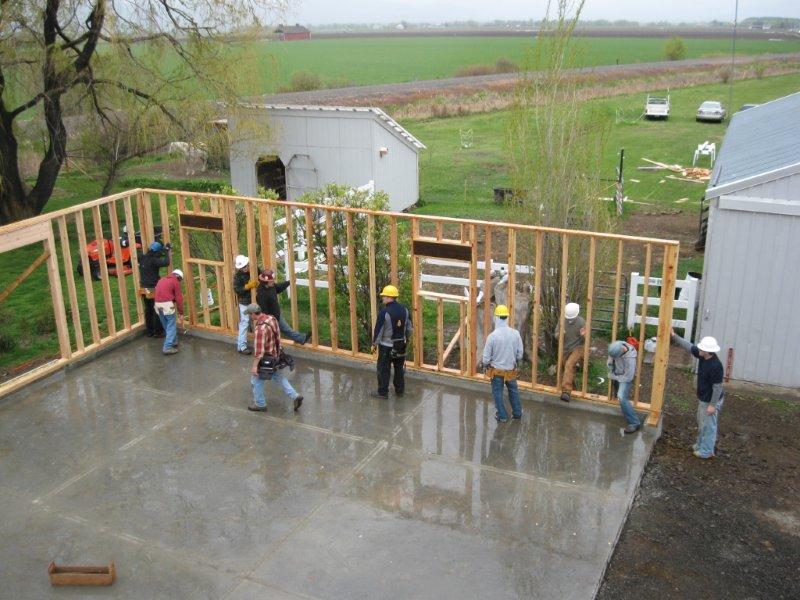
The CWU Construction Management
class CMGT 245 starts the garage framing (May 10, 2010).
|
- |
|
|
 |
|
-
Week
10:
What
is due:
Final
Project Elevations due on Tuesday in the box after class. |
|
Hand in your elevations for
your Final Project in a similar manner as your textbook elevations.
Look at and correct your markups from 2 weeks ago to ensure that you do
not repeat the same mistakes. You must include your floor plan(s)
also with this assignment. The elevation must be at the same scale
as your floor plan. Hand in only 2 sides, the front and one of the
side views. This assignment allows me to give you some feedback before
your final.
Design a north arrow for
your Final Project site and floor plans. Consider some design ideas
that you can find on the web. Below are some images of some CAD files
of north arrows from some drawings that I have run across. The north
arrow images that follow the north arrow examples are what I consider to
be great designs from previous students. This arrow will be due on
Tuesday in Week 11 as part of your examination.
Your north arrow must be
unique, done in CAD (no images) and it must fit in about 1" to 1-1/2" square.
Your work must be unique, there are plenty of arrows available on the web.
If you get a zero on this portion of your examination, that will be more
than 6% of your grade.


|
- |
|
|
 |
|
-
Week
11:
Your
last exam will be on Tuesday.
On Tuesday
and Thursday we will set up our remaining sheets and work on our Final
Project. |
|
Exam on Tuesday, similar to
the previous exam.
We will cover items related
to the Final Project both on Tuesday and Thursday including setting up
our remaining sheets.
|
- |
|
|
 |
|
-
Information on your Final
Project follows below:
-
Your project will consist of
various sheets, named a Sheet Set, designed similar to what we have been
doing in class. What your are producing is a set of construction
drawings that could be used, with some additional refinements, to construct
your home. These sheets include:
-
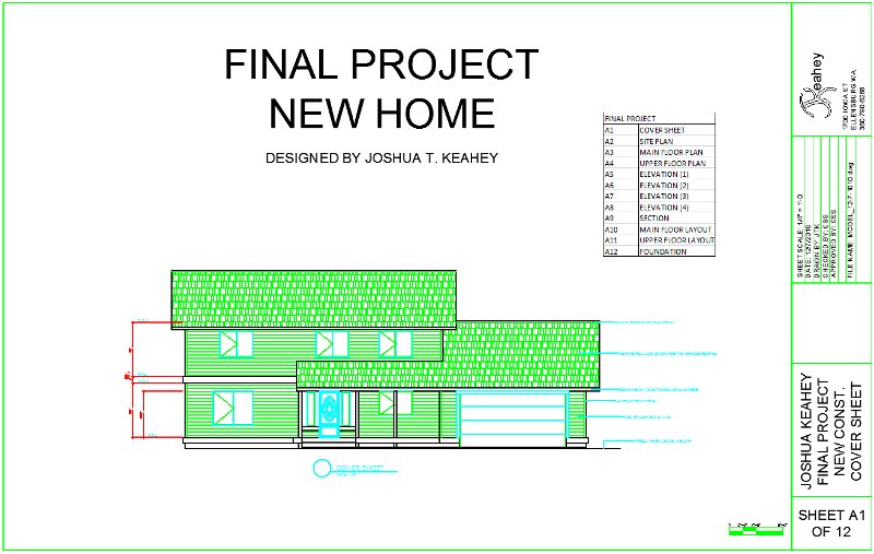
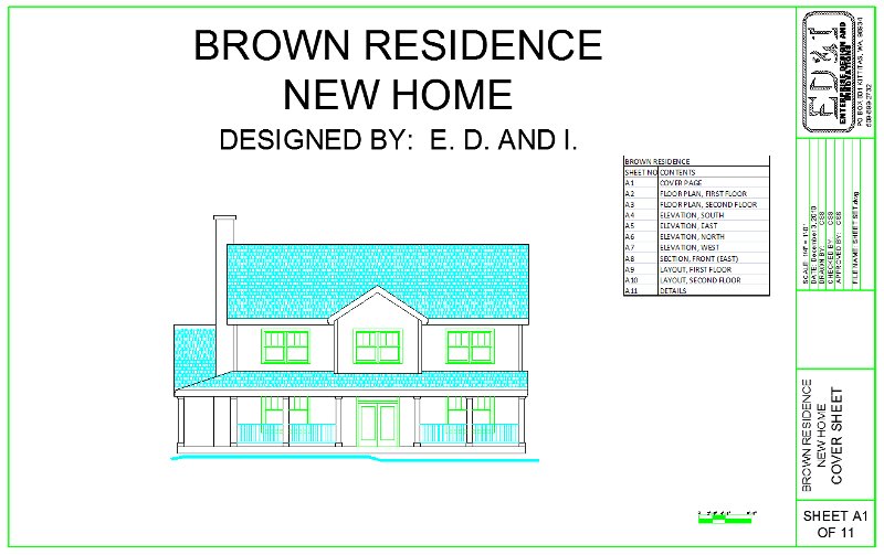
A1, Cover page, information
including table of contents and an embellished elevation (hatches, colors,
blocks) of the front of your house (dress this up and print in color)
-
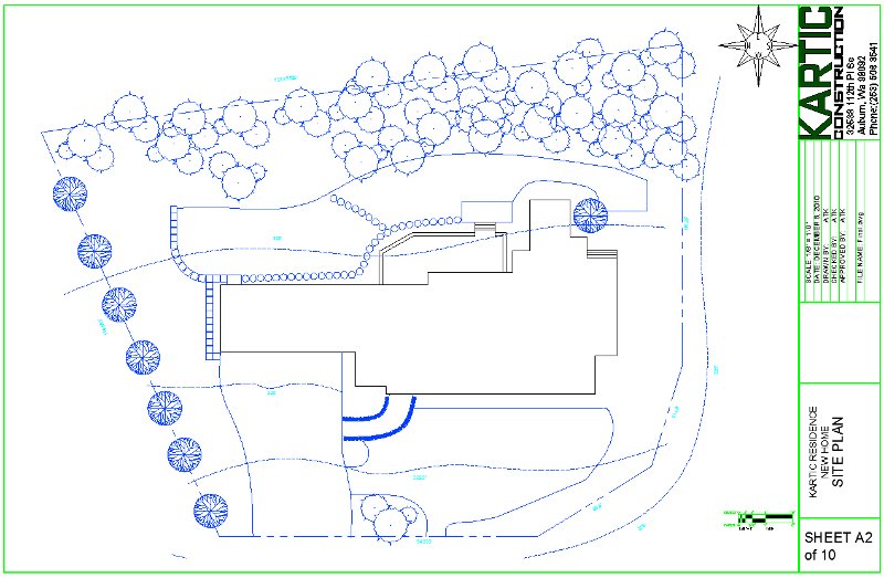
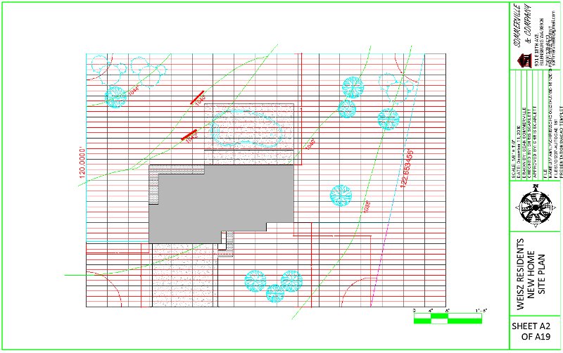
A2, Site Plan, per the text
book
-
Download this file, at the link
below, for a dynamic block "Scale Bar" to be used on your site and floor
plans. Instructions are included with this drawing file:
-
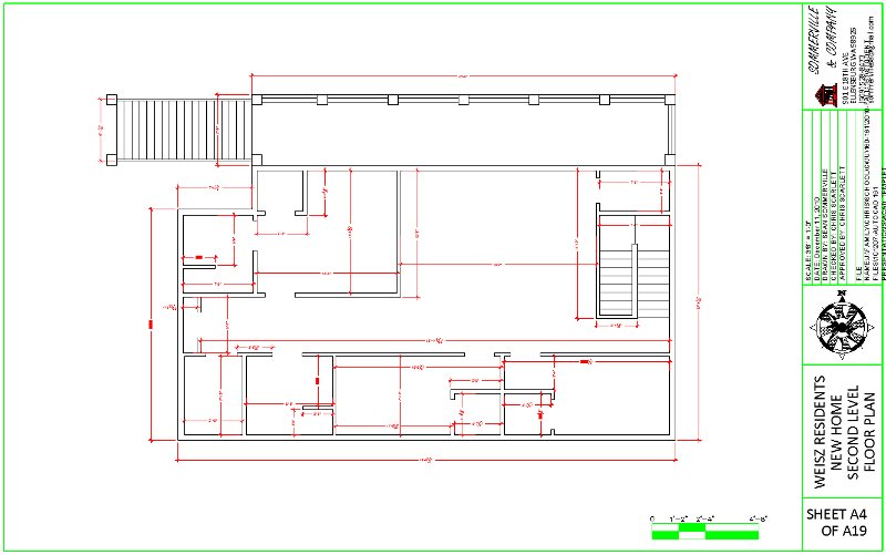
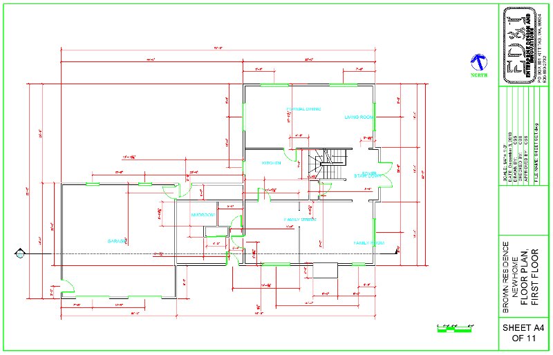
A3 and A4, Floor Plans, first
and second floors (foundation plan is extra credit)
-
At least 8 rooms per floor (not
including closets) or 16 rooms on a single floor (stairwells and long hallways
are considered rooms for this evaluation).
-
Include a garage (not considered
a room)
-
Include all rooms that would
be appropriate for a house of this size including a laundry room and office.
-
A5 through A8, Elevations of
all four sides, no hatching for these views
-
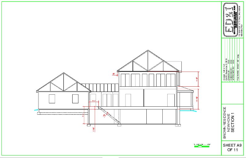
A9, Section of your choice (more
than one section for extra credit)
-
A10, Layouts of one of your
floor plans.
-
Include at least one instance
of all of the blocks from your architectural objects. You also must
include some items from the AutoCAD Tool Palette or Design Center (a kitchen
without a refrigerator or dishwasher would be rather incomplete).
-
Include counter tops for your
kitchen(s), bathroom(s) and closets
-
Extra credit for a layout of
the other floor and basement.
-
A11, Details (at least 4 details
with dimensions on a single sheet, extra credit for more)
-
So far, 11 sheets.
-
The sheets for your project
will be handed in on the day of the final to be printed before class
(penalties for printing during the final).
-
Print a full size sheet in color
for the Cover Page (to be displayed in the lab)
-
Print half size sheets in grayscale
for the rest of the project including the cover page to be handed in after
your presentations for grading.
-
You also need to hand in your
preliminary Final Project floor plans and elevations, that were previously
marked up, along with your printed Sheet Set.
-
Your Final Project will be evaluated
by your peers in class as well as by me. A form will be available
soon and will include criteria similar to the list below:
-
Completeness
-
Complexity and Effort
-
Design Quality (does it look
attractive, is it put together correctly?)
-
Design Function (does it function
properly, doors and windows in good locations, room placements, counter
tops, traffic flow, etc... ?)
-
Presentation (spoken clearly,
easily understood, showed everything...)
-
Overall Impression
-
Sheet Set grading criteria is
based on the projects that we have been doing all quarter. Check
your past assignments and markups for guidance.
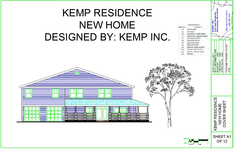
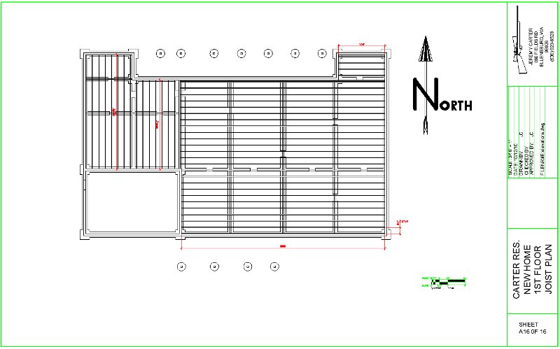
Below are some screen shots
of the Print Previews for some of the sheets in my sample Final
Project. What is shown below is a demonstration of how sheets can
be laid out. How you layout your sheets is to your discretion as
long as the information that I am looking for is there and it is displayed
using criteria that we have been using all quarter.
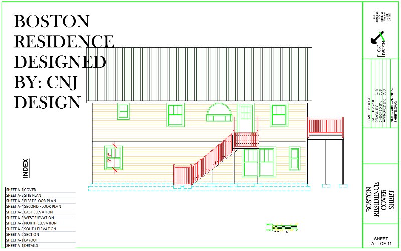
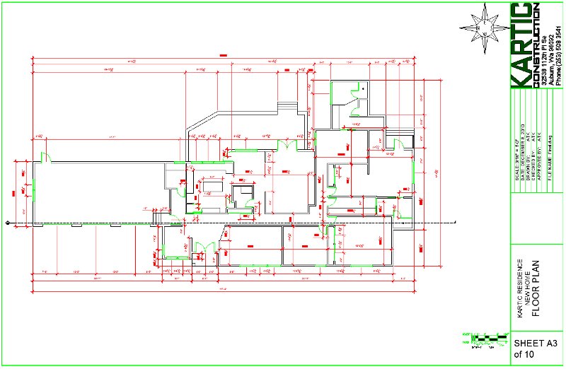
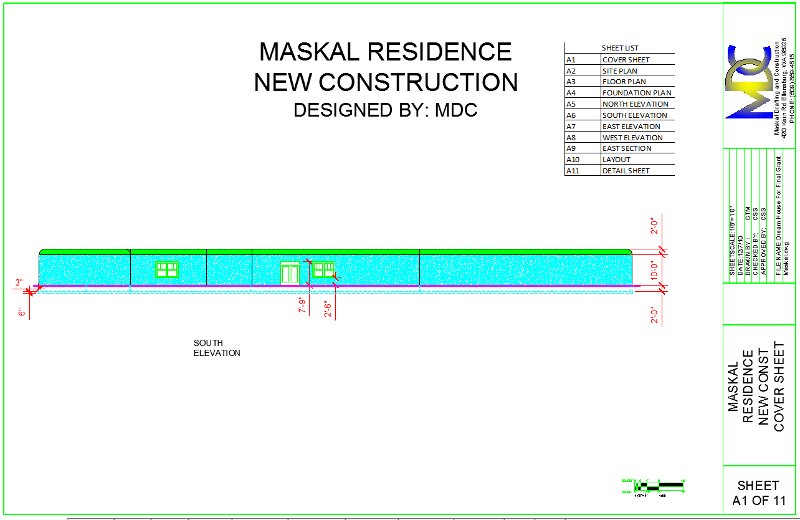
Sample Cover Sheet, notice
the Excel generated sheet list, scale bar and updated Title Block with
this sheet's unique information. Scale on this viewport is 1/4" =
1'-0" (48) (half the scale of your textbook house because it is now on
a full sized sheet) the scale bar reflects this scale. Some sheet
notes pertaining to the whole project may be relevant on this sheet.
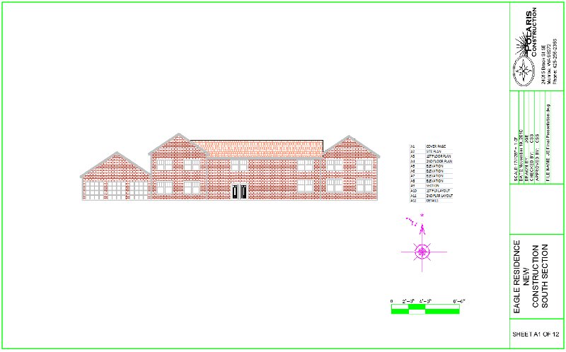
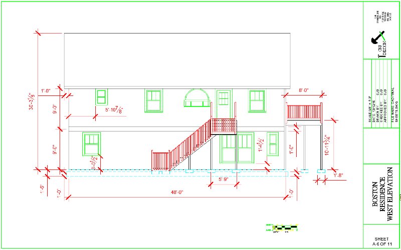
Notice the scale bar and
north arrow and updated Title Block. The scale on this viewport is
now 1/8" = 1'-0" and the scale bar reflects this. Insert the scale
bar and north arrow in paper space so you do not have to scale these up
or down. The scale bar should always be inserted at 1:1 in paper
space.

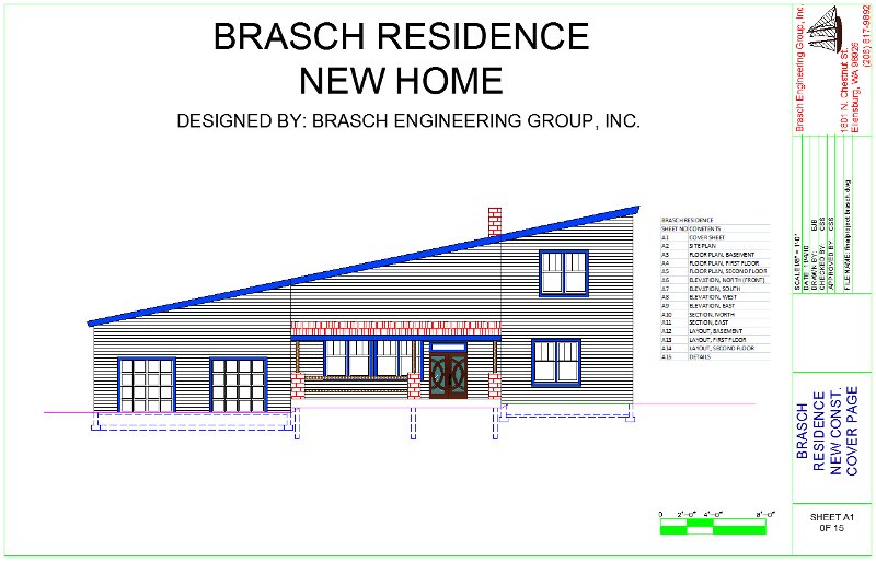
Notice the scale bar and
north arrow and updated Title Block. The north arrow is inserted
on every plan sheet and the scale bar on any sheet with dimensions in a
viewport of a specific scale (the scale bar will reflect this scale).
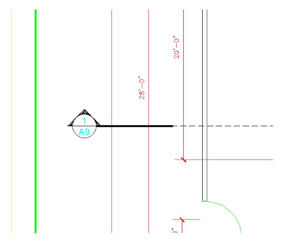
Also notice the section symbol and its direction of cut. A close
up of the symbol can be found in the following image.
Close up of the section symbol.
The text in the symbol refers to section 1 on sheet A9. A detail
symbol with text is similar with out the line and hidden line extension.
A sample sheet for an elevation.
There will be no hatches in this view but include all relevant dimensions
once on at least one of the elevation sheets. The scale bar is on
this sheet also.

This is a sample section
sheet, it is more common to have multiple sections on a single sheet.
This is a sample layout sheet.
The placement of your furniture is at your discretion.

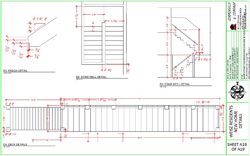
This is a sample details
sheet, it is common to have multiple details on a single sheets since they
can be scaled down quite a bit. Notice that the scale section in
the Title Block says "As Noted". This means that each view will have
its own scale notation. A view title with the relevant information
is included with each view and a close up is shown in the following image.
A scale bar should be included with this sheet.

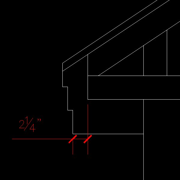
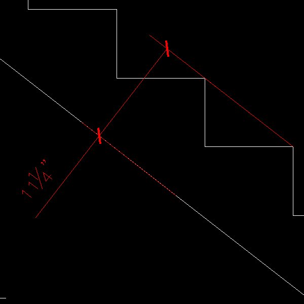
Close up of the house fascia
detail. Notice the View Title with a detail number, description and
scale.

|