IET
161.001 Architectural
CAD (Computer Aided Design) (Using
AutoCAD 2012 and Revit Architecture 2012) Fall
Quarter 2011
The
end of the quarter
December,
2011
Your
Final Commercial Project grades have been compiled and your grades for
the quarter have been posted.
The website
has been updated reflecting your commercial project images and Walk Throughs
and are available in the Design Gallery section below.
Some images and Walk Throughs need additional work, probably by tomorrow.
This
has been a great class and it was a pleasure teaching and training everyone.
For only the second class like this, taught at Central, the quality of
the work produced was extraordinary as was reflected in you Commercial
Projects grades. I hope that all of you get a chance to use this
or a similar program again in your careers ahead. Call or email sometime
if you have any questions regarding Revit or AutoCAD, or just to let me
know how you are doing.
Videos
of your Walk Throughs are available in the Design Gallery
section below.
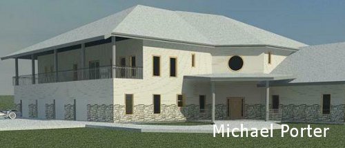
The student
with the best Overall ranking from Week 7's Dream House project
student evaluations was Michael Porter. His and the other renderings
from your Dream House project are available in the Design
Gallery section below.
In this
section, for every week, there will be a listing of what is due for that
week. You will practice and produce the assignments listed in this
box for handing in or to prepare for an In Class Evaluation (ICE) demonstrating
the skills learned. See the syllabus for assessment details.
Design
Assignments due this week:
For next
Tuesday come to class with sketched floor plans of a Dream House that you
would like to design. You will be modeling this project both in AutoCAD
and Revit later in the quarter but for this assignment produce a paper
and pencil sketched drawing of both the first and second floor of a house.
In this
section will be information on what should be read, practiced and produced
before
coming to class for the week. Plus it may contain announcements relevant
for that week's class.
Announcements:
You should
have bought the following book from the Wildcat Shop, Introducing Autodesk
Revit Architecture 2012, by Patrick Davis. If you bought the
2011 version instead please return it to the bookstore and exchange it
for the 2012 version.
Read
and practice ahead:
See Week
2 for details on what should be read and practiced for Week 2.
Class
exercises and assignment details:
See Week 2 for details on
your Sketched Floor Plans assignment
-
-
Week
2:
Design
Assignment due:
(this
is a repeat of what was listed for Week 1) On Tuesday come to class with
sketched floor plans of a dream house that you would like to design.
You will be modeling this project both in AutoCAD and Revit later in the
quarter but for this assignment produce a paper and pencil sketched drawing
of both the first and second floor of a house. See details
below.
Read
and practice ahead:
View
the following videos from the Autodesk website for AutoCAD 2012.
Download,
view, print (if you like), read and practice the first three tutorials
from the Autodesk website for AutoCAD 2012 (apparently these are the same
as the 2011 versions). Download and then unzip the downloaded files
on your flash drive or network save location:
You may
also download Tutorials 4 and 5 if you like for use next week to save time.
AutoCAD
has various training aids that you may also find useful. A link to
the Autodesk website with these tools are available at the following link
(we will cover only a few of these in this class as listed above):
Sketched Floor Plans Assignment:
Your sketched floor plan
will be graded on the following criteria, Click
here for your ICE grading criteria. Download and print out the
grading criteria before class on Tuesday, sign your name, fill in the date,
staple it to your assignment and hand in all of the related documents at
the instructor's desk.
For this and all assignments
your work has to be original and unique or you will get no points!!
For your sketched floor plans,
put some thought into this project. You will refer to these sketches
in a few weeks and use them to generate your computer models in AutoCAD
and Revit. Try not to make it too big, it will mean a lot of work
for you later.
Requirements for your first
and second floor sketches.
ANSI A size sheets (8-1/2" by
11") one sheet per floor, landscape orientation
Draw the first floor first
Draw the second floor so that
it is on top and lined up with the first floor when the sheets are together
No scaling
No wall thickness
use a single line to denote
interior and exterior walls.
Label all rooms with room names
At least 8 rooms per floor (not
including closets)
3 bedrooms at least
Front and back doors at least
Include a garage, attached or
detached (not considered a room)
Include all rooms that would
be appropriate for a house of this size including a single utility room,
laundry room and office
Extras may include landscaping,
decks, furniture, etc...
Class
exercise:
Click
on the following link and extract this file for AutoCAD files that
will be used as a demonstration in class on Tuesday.
Out
of class exercises:
Practice
and produce the following exercises, draft these as separate files with
the appropriate title block updates as described in class on your renamed
Template1.dwg file. One of these will be due at the time of the In
Class Evaluation at the beginning of class on Tuesday in Week 3.
TOY
HOUSE
CONCRETE
MASONRY UNIT (CMU)
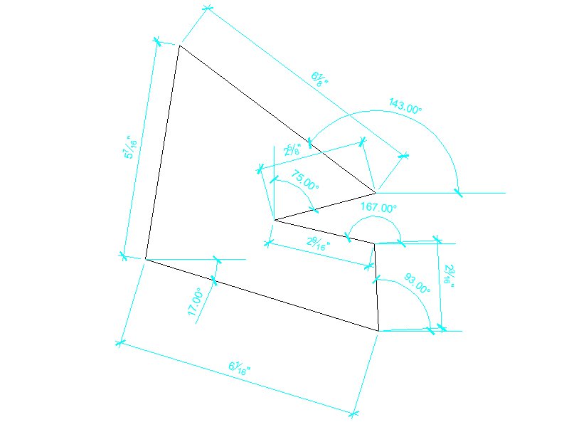
WHEEL
IRREGULARIS-1
IRREGULARIS-2
BOOKSHELF
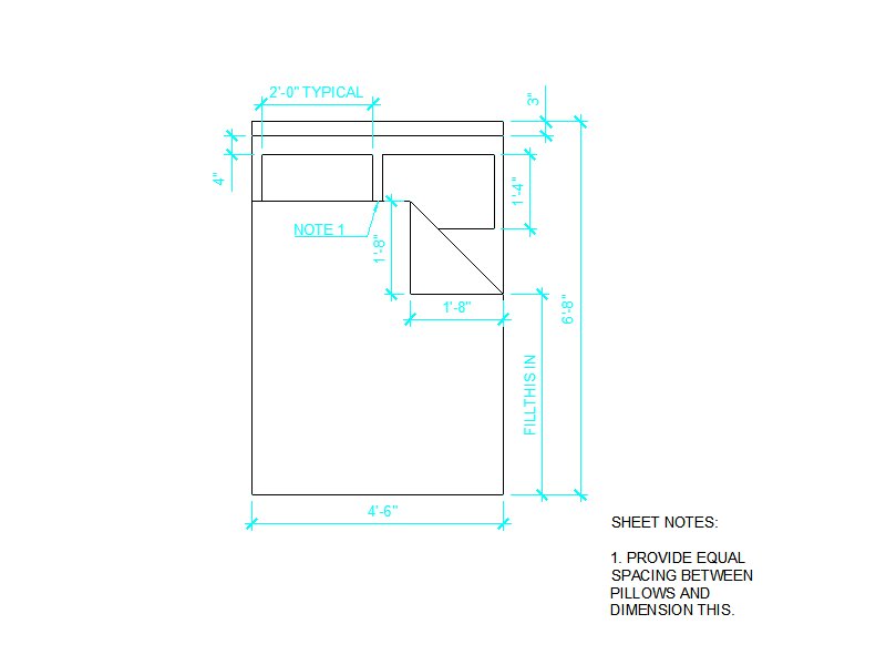
DOUBLE
BED
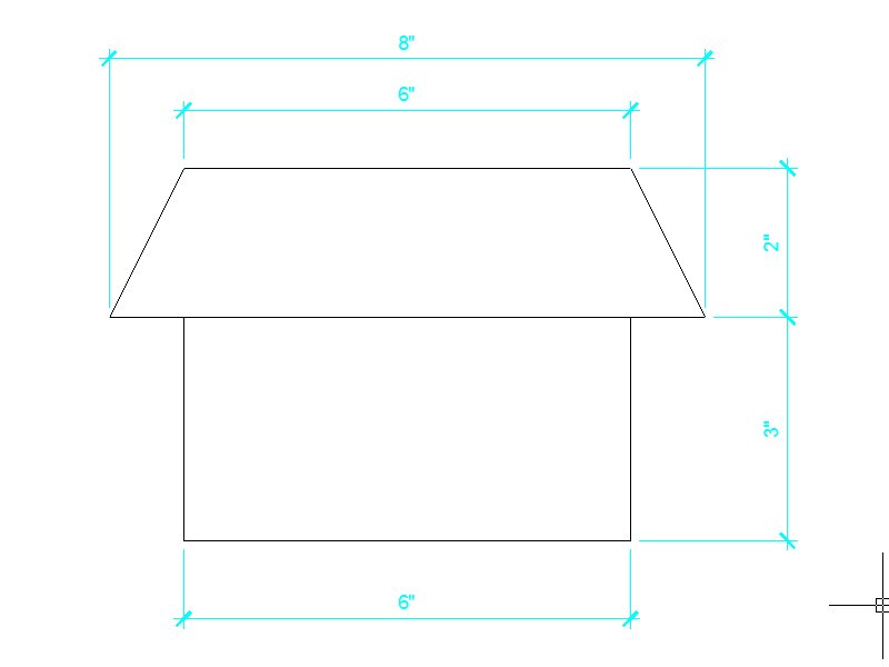
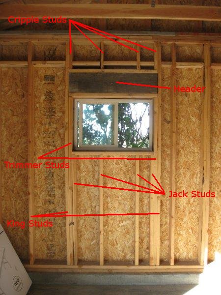
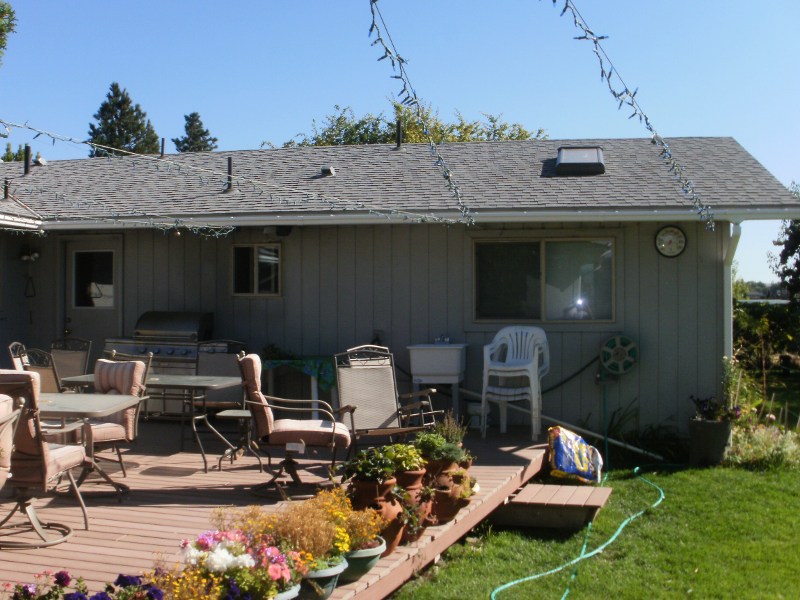
HOUSE
ELEVATION IMAGE
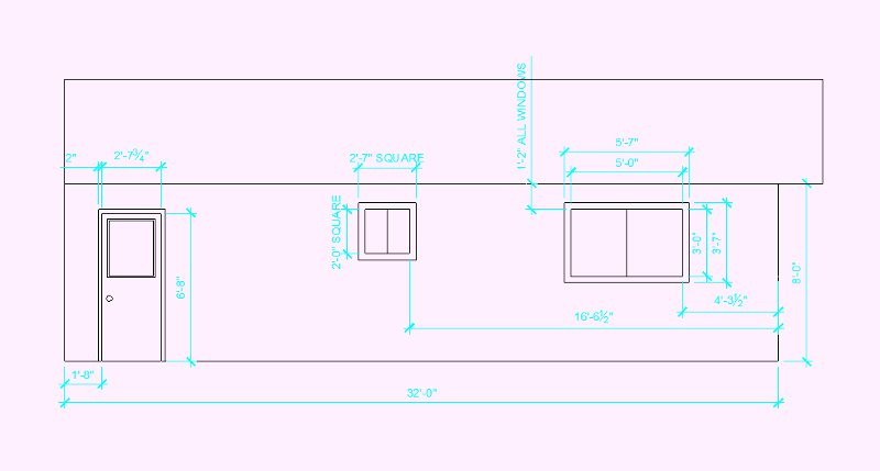
Use
an image like this or draft a likeness of your own wall from your dream
house design. You need to know some dimensions in order to draft
to scale similar objects in your drawing. The walls are 8' with a
roof overhang of 2'. The back door is 80" by 31-3/4" at the opening
with 2" brick mold. The window trim is 3-1/2" and the grooves in
the siding are 8" wide.
HOUSE
ELEVATION DRAWING
HOUSE
ELEVATION DRAWING WITH HATCHING
-
-
Week
3:
Design
Assignment due: For
your ICE (In Class Evaluation) on Tuesday you will be required to hand
in 3 items:
Produce
the exercises from Week 2, one of these will be handed in.
Measure
and draft, in AutoCAD, a wall elevation.
Produce,
in class, an exercise that will be presented on the projector.
Read
and practice ahead:
View
the following videos from the Autodesk website for AutoCAD 2012.
Download,
view, print (if you like) read and practice tutorials 4 and 5 from the
Autodesk website for AutoCAD 2012 (2011). Download and then unzip
the downloaded files:
In Tutorial
5 we will not be covering, in this class, the different linetypes (we will
stick with the basic solid line) and lineweights (we will stick with the
default size).
Produce the exercise from the
projector at the beginning of class.
This exercise
will be similar to the exercises from Week 2 and you will have 20 minutes
to complete it.
Hand in one of the exercises
from Week 2 as instructed during the evaluation.
Hand in the Wall Elevation Assignment
per the instructions below:
Choose a wall and draft an elevation
of this wall using your template file, re-save your template using an appropriate
name.
Any wall type, inside or out,
you may draft a wall from your sketched floor plan.
Measure this wall using techniques
discussed in class
Draft in Model Space, print
in Paper Space
Must contain at least 10 elements
(elements are considered some sort of enclosed geometry such as rectangles,
circles or ellipses).
Dimension in a manner similar
to the exercise in Week 2
Orderly and easy to read
Not covering objects or other
dimension lines (like the 2" dimension for the door trim)
include both horizontal and
vertical location dimensions
Measure from walls for horizontal
window and door locations
Larger dimensions on the outside,
shorter dimensions on the inside
Use appropriate scale so it
fits on your A sized template file in Paper Space.
Title block updates.
Out of
class exercises:
Practice
and produce the following exercises, draft these as separate files with
the appropriate title block updates as described in class on your renamed
Template1.dwg file. At least one of these will be due at the time
of the In ICE at the beginning of class on Tuesday in Week 4.
-
DOUBLE
BED
ARCHITECTURAL
OBJECTS
Make
Blocks out of these objects and include them into your floor plan.
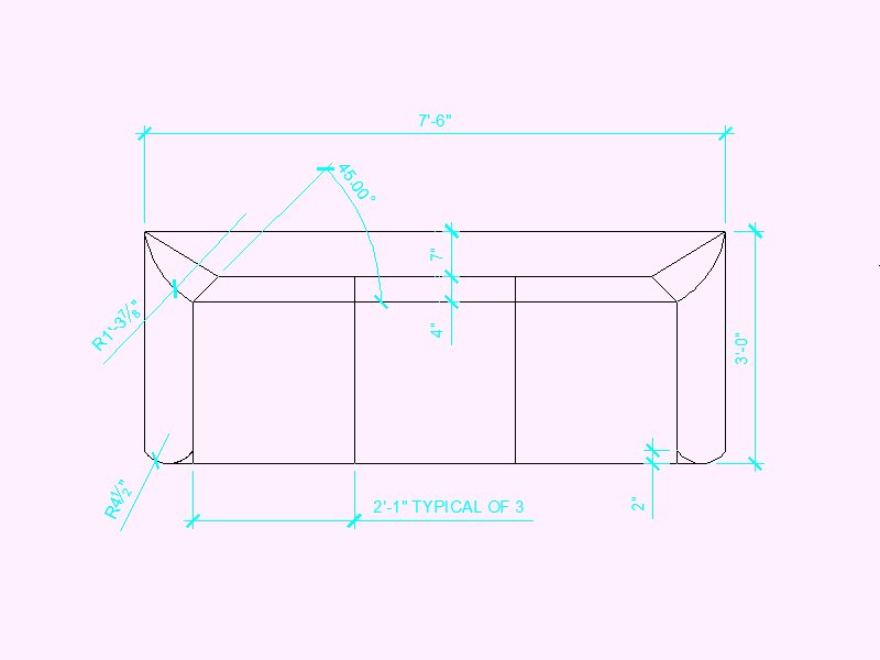
THE
COUCH
Also
create a love seat and single seat using the same design as below.
Make
Blocks out of these objects and include them into your floor plan.
STAIRS
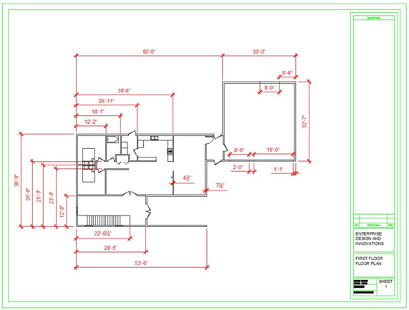
FLOOR
PLAN SAMPLE
Draft
your own floor plans, both first and second floors using your sketches
from Week 2 as guides.
-
-
Week
4:
Design
Assignment due: For
your ICE (In Class Evaluation) on Tuesday you will be required to hand
in 5 items:
Produce
the exercises from Week 3, one of these will be handed in.
Draft, in
AutoCAD, your floor plans (2 total) of your dream house that you hand sketched
from Week 2, hand in the hand sketched floor plans also.
Produce,
in class, a floor plan exercise that will be presented on the projector.
Read
and practice ahead:
Your
Revit textbook, chapters 1 through 4. Read and practice these before
class on Tuesday.
Class
exercises and assignment details:
In Class Evaluation (5 items)
Click
here for your Week 4 ICE grading criteria.
You
will print out and hand in the 5 items listed below stapled to your ICE
Grading Criteria. Place your drawings in order.
Produce the exercise from the
projector at the beginning of class. This will be small floor plan
of an apartment, you will have 30 minutes to complete
it.
Hand in one of the exercises
from Week 3 as instructed during the evaluation. You do not have
to complete the Stair elevation exercise.
Hand in your Dream House Floor
Plan Assignment per the instructions below. 2 sheets plus your hand
sketched floor plans from Weeks 1 and 2 (3 items total) (40 points total
(20 points per sheet)):
Using your sketched drawing
as a reference from Weeks 1 and 2 draft both your first and second floor
plans, both the hand sketched and CAD plans must be similar.
One floor per sheet, 2 sheets
total.
Sheets are aligned from 1st
floor to 2nd floor
Must contain the rooms and elements
from your sketched floor plan although some minor variations are permitted
At least 8 rooms per floor
3 bedrooms at least
Front and back doors at least
Garage with doors openings
Stairs similar to the example
in Week 3, provide a landing on the top and bottom
Insert blocks
7 blocks made in Week 3; the
2 sinks, washer, dryer and the couches (3)
Various blocks from the Design
Center drawing, including the dynamic blocks for the doors and windows,
10 minimum
Dynamic blocks must have the
wall thickness settings changed (call me if you need help on these).
Dimension interior and exterior
wall locations only, in a manner similar to the floor plan example in the
Week 3 section above.
Overall house dimensions
Orderly and easy to read, not
covering objects or other dimension lines
Dimensions for the interior
walls from a common exterior outside wall edge as shown.
Be consistent regarding which
interior wall edge used
Whole foot and inch units (no
fractions (exceptions for the stairs and instances involving wall thickness
issues)).
Larger dimensions on the outside,
shorter dimensions on the inside
Dimension once each of the 2
wall thicknesses, interior and exterior (similar to the example in the
Week 3 section above)
Appropriate dimension scaling
Use appropriate sheet scale
in the viewport so it fits on your A sized template file in Paper Space.
Appropriate title block updates
Extra credit for extra details
(extra rooms, counter tops, extra blocks, landscaping, etc...)
More details later, check
back
Out of
class exercises:
Download,
from the publishers of the Revit textbook, various files related to the
book. For Thursday's class download a file in the Chapter 2 Resource
File section by clicking on the HTTP link and downloading the "029961c02_dataset.zip"
file. Once downloaded, unzip this file into a folder on your flash
drive or network save location. From this folder open the file named
"Dataset_02_03.rvt" . This Revit file is the model that you see on
the cover of the book and is referenced various times throughout the book.
We will be taking a tour of this model in class on Thursday.
Start
on your Dream House floor plan using Revit by laying out the walls from
your AutoCAD floor plan. A portion of your Revit floor plan will
evaluated next Tuesday for your ICE.
Consider
the following when laying out your floor plans for your Dream House:
Bathroom
locations should be such so that the occupants of the room will not be
visible in an adjacent room when the bathroom door is open. Perhaps
locate the bathroom in a hallway.
The kitchen
should be close to the front door and entry from the garage. The
kitchen is considered a destination or departure point when entering or
leaving the house.
Consider
a mudroom adjacent to the front door, backdoor or garage. A mudroom
serves as a transitional room to put on or remove coats and shoes.
It also serves as a stop for outside air entering the house when the exterior
door is opened.
Follow
the steps for Defining Wall Structure starting on page 104
in your textbook. An exercise like this will be part of Week 5's
ICE. More information to follow, check back.
-
-
Week
5:
Design
Assignment due: For
your ICE (In Class Evaluation) on Tuesday you will be required to email
2 items:
Your Dream
House model produced & designed in Revit.
Produce
the 3 wall types (named as Defining Wall Structure in the text book),
one as described in the textbook and the two others as demonstrated in
class. These walls will be included in your Dream House model.
Produce,
in class, a simple Revit model of a simple home.
Read
and practice ahead:
Your
Revit textbook, chapters 4 and 5. Read and practice these before
class on Tuesday.
Produce the exercise from the
projector at the beginning of class. This will be simple home design.
You will have 30 minutes to complete it. You
will be graded in a similar manner as described for your Dream House evaluation
below.
Send in your Dream House model,
you will be graded in two parts, the first on the Defining
Wall Structure .and the second on your Dream House design
Produce
the 3 wall types (named as Defining Wall Structure in the text book),
one as described in the textbook and the two others as demonstrated in
class.
Name these
as described in the book and in class
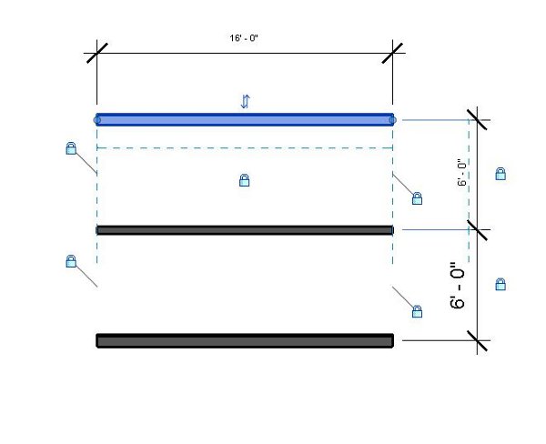
Place these 3 walls in front
of the north elevation symbol on the north side of your home, parallel
to the north wall on your house.
Make each wall 16 feet long
and 6 feet apart from each other and place permanent dimensions on them.
Lock these dimensions
Refer to the image below.
"Align" the edges of the walls
to each other and lock this constraint.
(You will know that you have
done the above steps correctly if all three walls move as one unit without
any walls being left behind, stretching or the dimensions changing.)
Your Dream House design in Revit
with the following elements:
3 levels, named (in CAPITALS)
FIRST FLOOR, SECOND FLOOR, ROOF
Level line and target are aligned
together and separated by whole or half foot increments
Exterior walls
Connected and oriented properly
From the FIRST FLOOR to the
ROOF level
Permanent dimensions in whole
or half foot increments
FIRST FLOOR Interior walls
Connected and trimmed
From the FIRST FLOOR level to
the SECOND FLOOR level
Permanent dimensions in whole
or half foot increments
Front door and windows of your
choice, 2 different window types with a total of 10 elements (read and
practice from the book for this function).
First and second floors of your
choice (read and practice from the book for this function).
Orientation of the 3
Defining
Wall Structure Walls located on the north side of your Dream House
Information on some basic
residential building design elements are shown in the images below.
The images for this week show various elements that go into a simple foundation
and first floor wall construction.
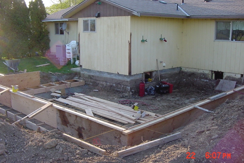
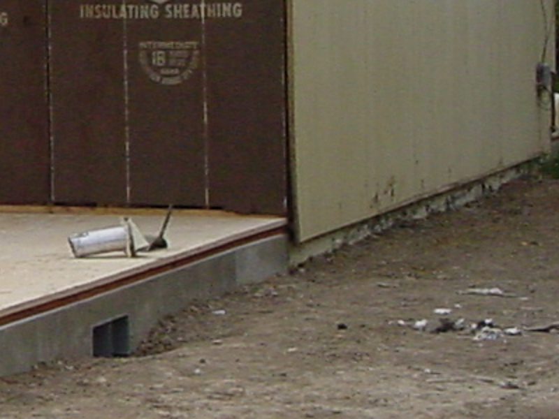
The image below shows the
site work prior to the setting up of the forms for a concrete foundation
footing and stem wall attached to an existing house providing a bedroom
addition.
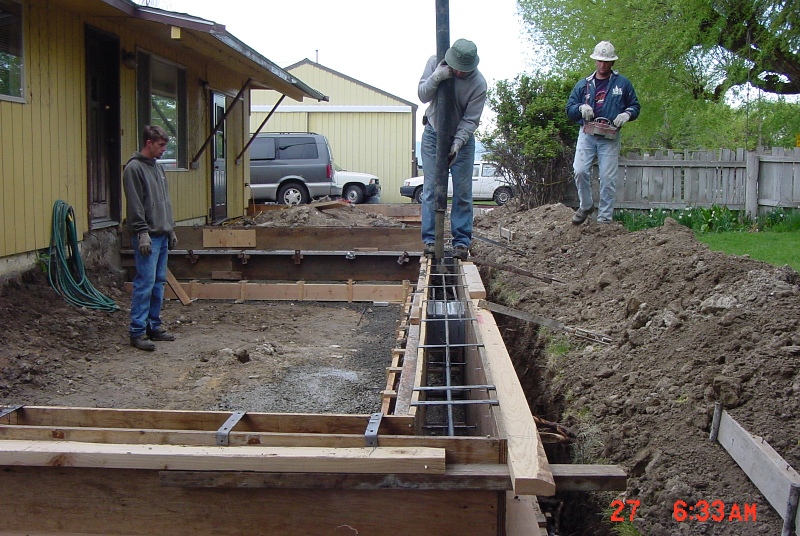
The forms as they are being
set up for the concrete.
The completed forms on the
front of the house as the concrete was being poured.
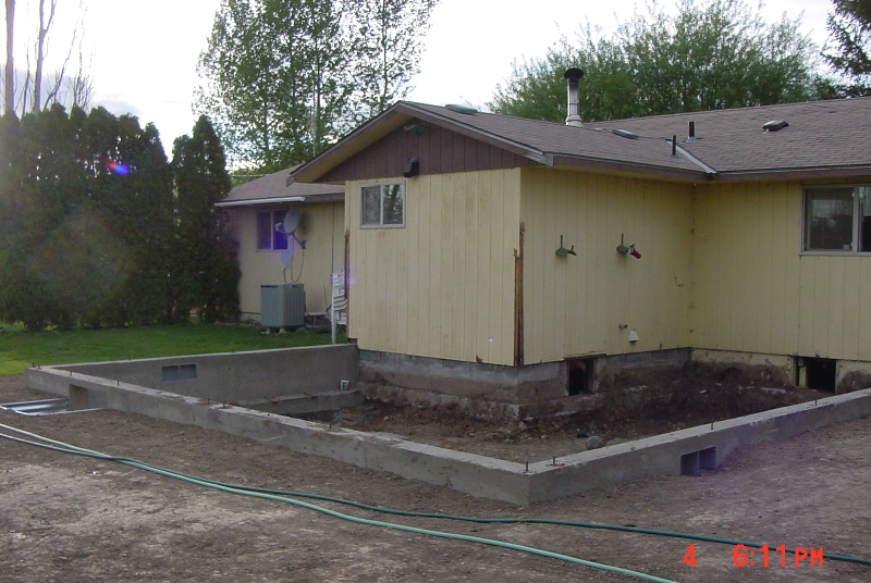
The new footing and stem
wall foundation.
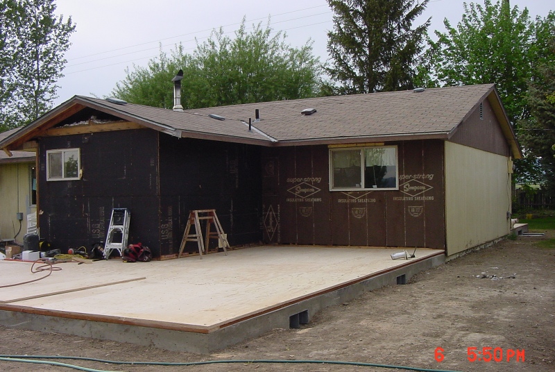
Two days later, the new sub-floor
is constructed on top of the new stem wall foundation. It is this
surface elevation, the top of this floor, that the floor plan with the
interior and exterior walls is designed from. Notice that the exterior
edge of the sub-floor is in line with the edge of the stem wall foundation.
The floor structure is an engineered floor joist system just below the
sub-floor and "hanging" by joist hangers from the inside of the stem wall.
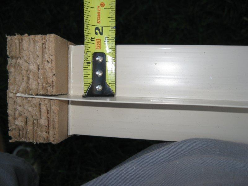
A close-up of the previous
image where the new addition meets the existing house. Notice how
the sheathing and siding covers the edge of the sub-floor and extends about
2 inches below the top of the stem wall foundation. This displays
the how the "Core Face: Exterior" edge of the first floor wall describes
how this wall structure is constructed and is in line with the stem wall
and sub-floor (as opposed to the finish faces or wall centerline).
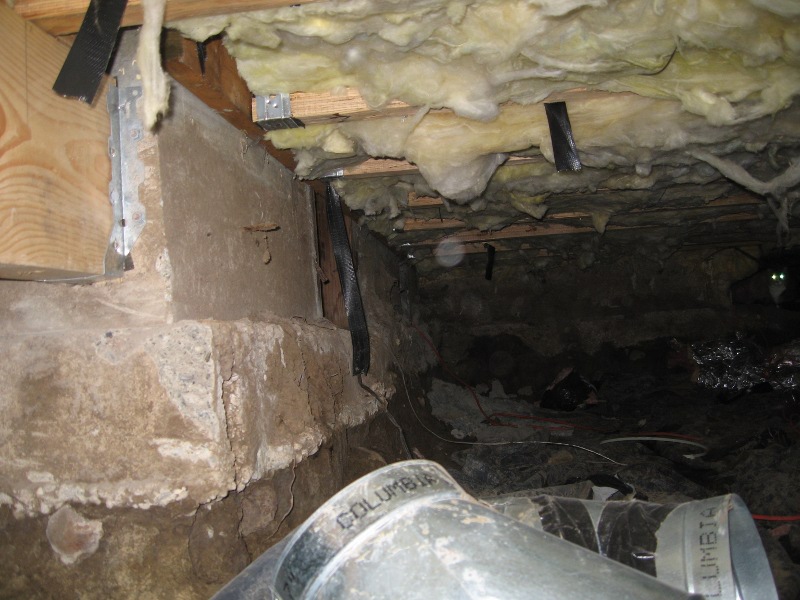
The image below shows, on
a separate job, how the floor joists are "hanged" from a plate. This
one is hanging off of another beam but the one on our house addition has
been hung on a plate attached to the concrete stem wall.
A corner of the existing
house showing the wall plate, hangers, center beam and floor joists as
well as the sandwiched insulation.
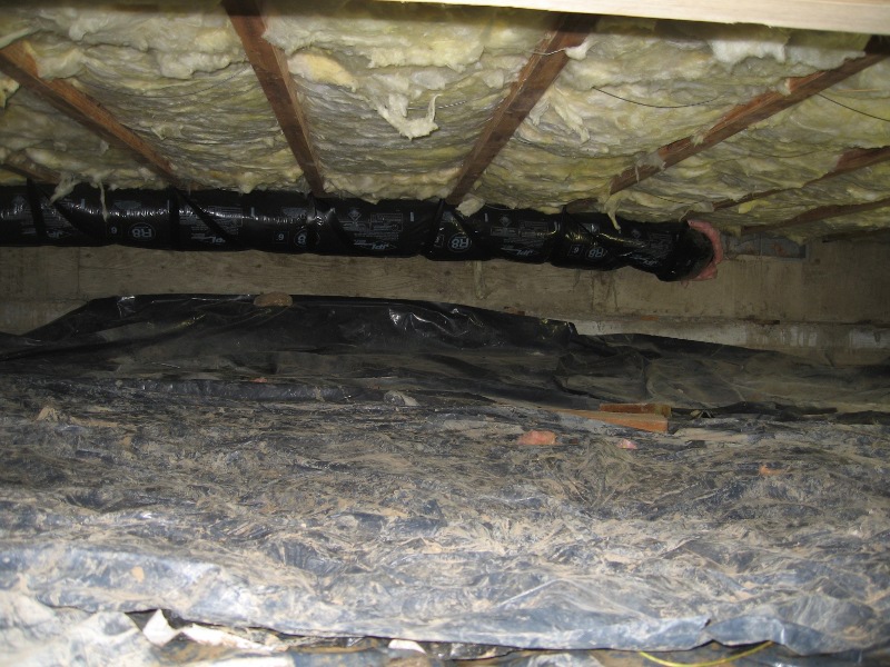
An image of the same space
looking to the right of the image above.
The inside of this space
showing the interior walls (2x4 construction, 3-1/2" wide) and exterior
walls with sheathing (2x6 construction, 5-1/2" wide). The sheathing
(1/2" plywood or OSB) is on the outside of the "Core Face: Exterior" plane
and before the "Finish Face: Exterior" plane so it is on the outside of
the exterior of the sub-floor and stem wall plane. To finish the
exterior walls you would add a layer for the dimensionless wind barrier
on the outside of the sheathing and then siding. On the inside of
the "Core face: Exterior" you would add the structure (2x6) and 1/2" drywall.
Occupying the same space as the structure of the wall (the 2x6) would be
the insulation. The interior wall sandwich would be 1/2" drywall-structure-
1/2" drywall, making the wall 4-1/2" thick.
-
Regarding the creation of
Revit Families:
The images below display
some of the dimensions associated with the construction of doors and windows.
We will not be covering the construction of Revit families but if you want
to pursue it on your own you may find the information and images below
useful. If you want to explore Chapter 17 you can use the information
below to help modify the existing families provided by Revit or to create
new ones.
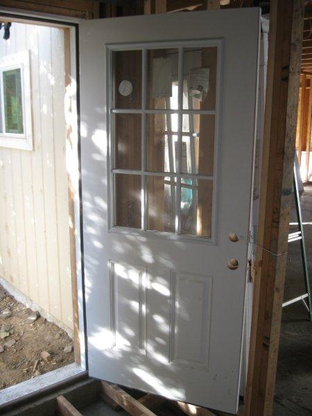
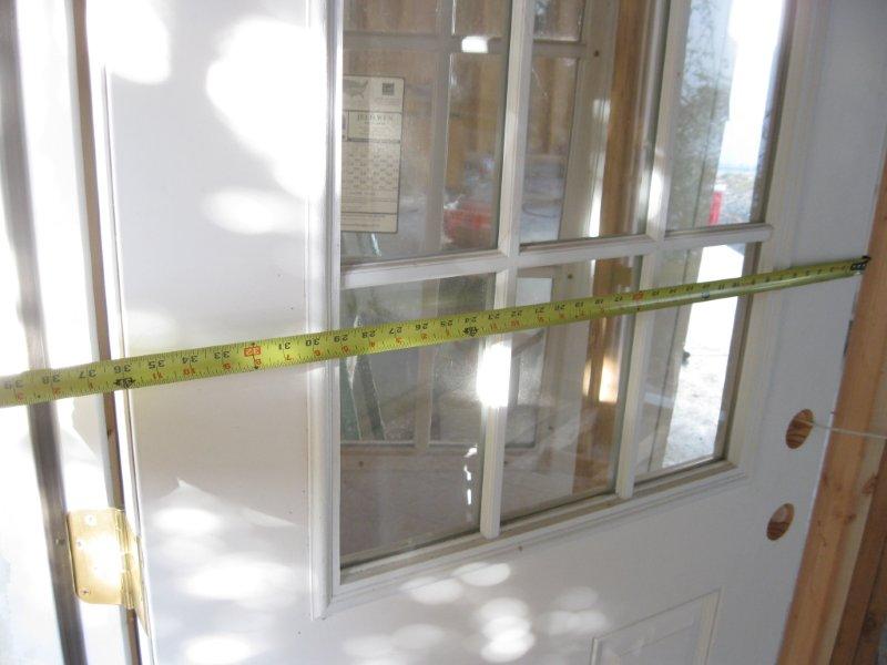
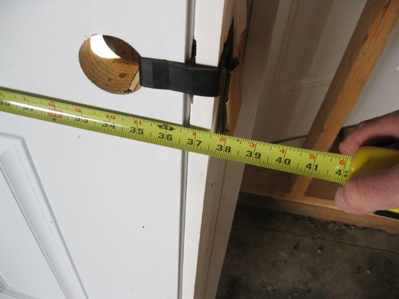
The immediate images that
follow show dimensions associated with a standard 36" door installation.
The image below is a 36" exterior door (6-1/2" exterior wall thickness).
The actual door size is 35-7/8".
The actual door size is 35-7/8"
(close up).
The exterior dimension size
is 40" including the exterior trim (brick mold).
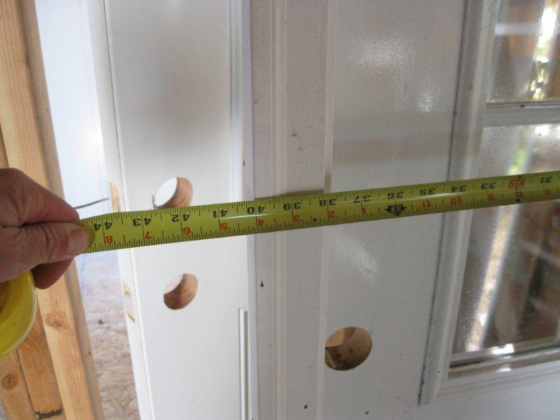
The actual opening of the
door, inside clearance is 36". This measurement determines the door
size.
The actual opening of the
door, inside clearance is 36" (close up).
The door frame on the interior
of this door is 37-1/2".
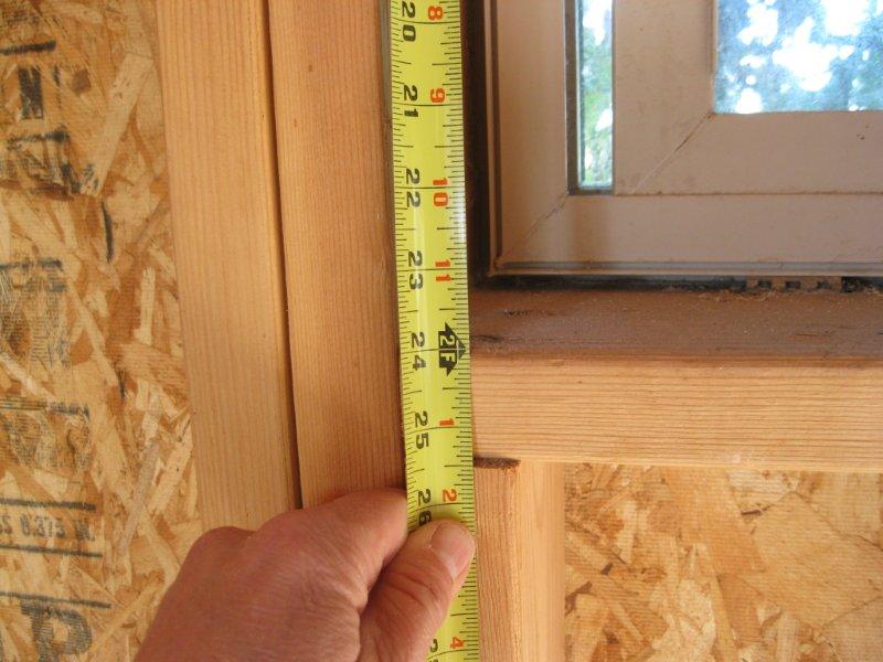
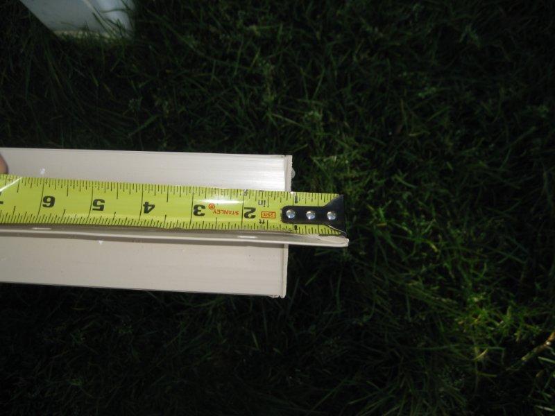
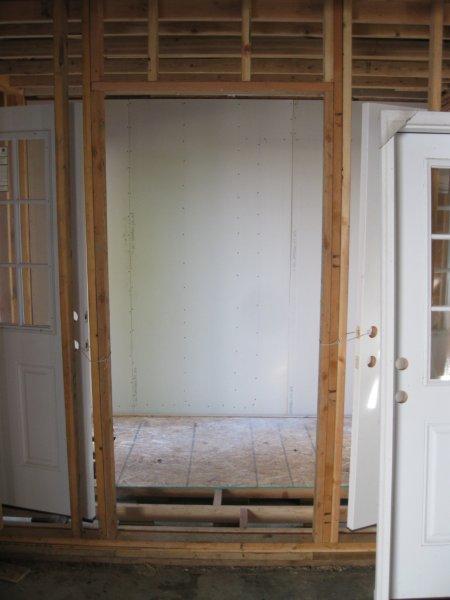
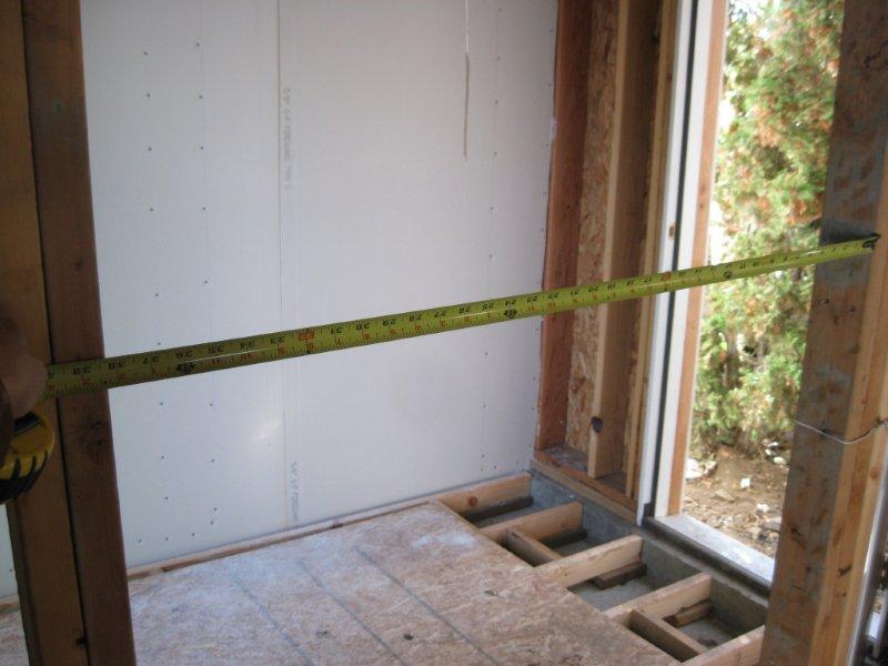
The images that follow show
dimensions associated with a standard 3' x 2' window installation. The
image below shows a framed window opening and window on the interior of
a garage for 3' x 2' window.
The framed window opening
(rough opening) for 3' x 2' window (close up). This is one of the
measurements that determine the window size.
The framed window opening
(rough opening) for 3' x 2' window (close up). This is one of the
measurements that determine the window size.
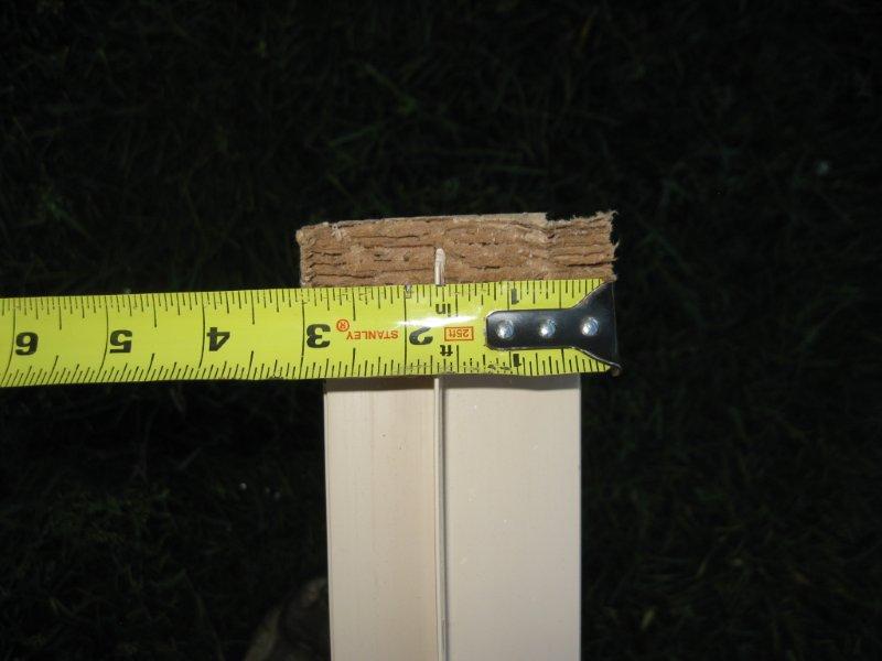
An uninstalled 3' x 2' window.
The window measures about a 1/2" less on each side referencing the window
size. This gives us about a quarter inch on all sides of the
window for adjustments, using shims, during installation.
Window and frame is about
3" thick.
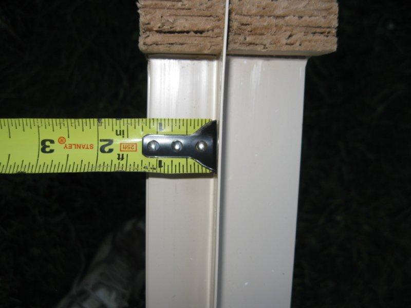
The nailing flange is positioned
about 1" back from the exterior edge of the window.
The nailing flange is about
1" long.
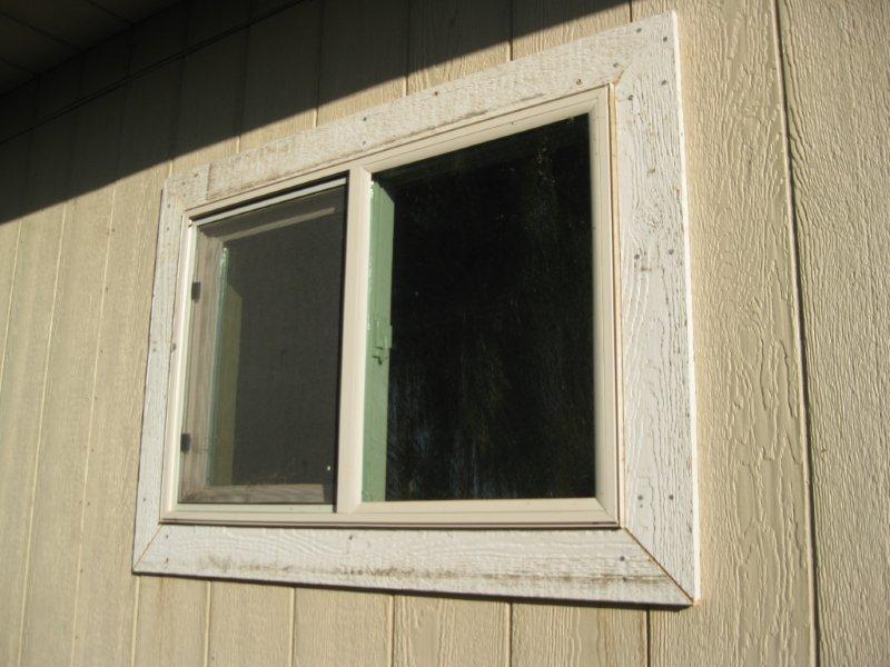
A finished window from the
exterior excluding caulking and paint, notice the nailing flange is covered
by the window trim.
A finished window on the
interior with a window sill. Revit will have library windows with
the trim and window sills included.
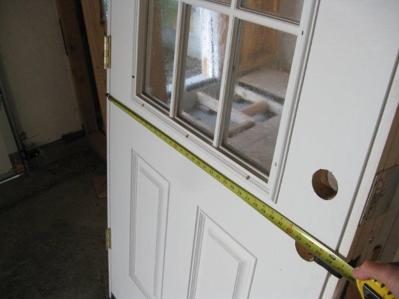
The door frame on the interior
of this door is 37-1/2" (close up). Allow for about 38" rough door
width opening. Revit will cut this out for you.
The framed door opening.
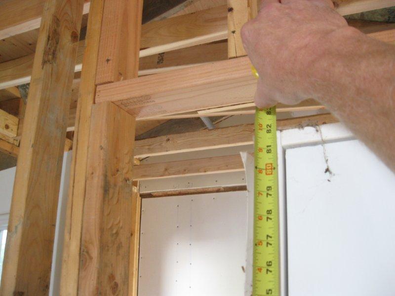
The framed door opening (rough
opening) height (about 81-3/4"). Allow for about 82" rough door height
opening. Revit will cut this out for you.
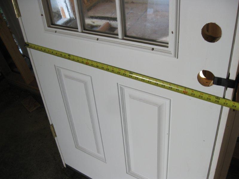
The framed door opening (rough
opening) width.
The framed door opening (rough
opening) width at 38-1/4" (close up) (usually 38"). This gives us
about a 3/8" on each side of the door for adjustments, using shims, during
installation.
-
-
-
Week
6:
Design
Assignment due: None
this week, your first midterm exam will be on Tuesday.
Read
and practice ahead:
Your
Revit textbook, chapters 6 and 7. Read and practice these before
class on Thursday.
Class
exercises and assignment details:
Your
first examination will be on Tuesday. To prepare for the written
portion of the exam you need to be certain that you have read and practiced
all of your reading assignments and have studied your notes taken in class.
For
the design portion of the exam you will be modeling a 2 story residence
in Revit. The residence model will incorporate many of the design
elements that have been demonstrated in class and include the following
elements:
3 levels, named (in CAPITALS)
FIRST FLOOR, SECOND FLOOR, ROOF
Level line and target are aligned
together and separated by whole or half foot increments
Exterior walls (developed in
Week 4)
Connected and oriented properly
From the FIRST FLOOR to the
ROOF level
Permanent dimensions in whole
or half foot increments
Dimensioned from the exterior
wall edges as shown
Interior walls (developed in
Week 4)
Connected and trimmed
From the FIRST FLOOR level to
the SECOND FLOOR level
From the SECOND FLOOR level
to the ROOF level
Permanent dimensions in whole
foot or inch increments
Dimensioned from a common wall
edge as shown, to the centerline of the interior walls
Room bounding with consecutive
numbers and names in CAPITALS
First and second floors (developed
in Week 5)
First floor 6" concrete slab
with floor covering (carpet, vinyl, wood etc...)
Second floor joist with floor
covering with 5/8" dry wall ceiling for the first floor
Front door, double door with
sidelights, double sliding back door
Interior room doors with trim
at 30"
Windows, 3 different window
types of your choice, head height consistent for all similar windows installed.
Edit profile of floor to cut
out area for stairs and railings
Alignment to adjacent wall
Curtain wall with mullions as
shown
Interior furniture and fixtures
of your choice, 20 unique ones minimum
More details later.
-
-
Week
7:
Design
Assignment due: Dream
House project presentation and model. Commercial Project proposal.
Read
and practice ahead:
Your
Revit textbook, Chapters 13 and 14. Read and practice these before
class on Thursday. We will save the Chapter 11, Rendering, for Week
9 when we have some work done on our Commercial Project.
Class
exercises and assignment details:
We
will also have a guest speaker on Tuesday, Stan Dudley who had helped develop
our department back in the 1960s. He will share some insights and
advice on drawing development comparing the similarities and differences
between the new ways and the old. There will be an opportunity for
a question and answer session. He will speak sometime during our
presentations.
Hand in
on Tuesday a proposal for your Commercial Project, discussing the following:
The type
of project (examples include: restaurants, schools, auto show rooms, hotels,
theaters, malls, grocery stores, coffee shops, etc... essentially any building
engaged in commerce that is open to the public)
How large
do you anticipate the project to be (described as rooms, square feet, floors,
etc...)
You need
to be certain that the project is adequately large enough to get a decent
grade for content but not so large as to risk running out of time to complete
it.
A maximum
size, should be no larger than about what can fit into a 400' x 300' rectangle
in a plan view.
A small
project needs to have extra details to make up for building size.
Your Dream
House project presentations and model will serve as a weekly In Class Evaluation
(ICE) for Week 7. Click
here for your Week 7 ICE grading criteria.
Print this out at the beginning of class on Tuesday. You do not have
to demonstrate a toolbar. We will save that feature for the Commercial
Project. Below is a list that can serve as a guide for your presentation:
Tour of
your house using the Project Browser as a guide
Start
with the site plan then a 3D tour of the outside of the house, then the
first floor plan starting with the front door and show how one would move
through the rooms of your house.
Display
the different elevations and sections and the features that these show
Finish
with camera views, photo renderings and a Walk Through (see instructional
link below)
Practice
your presentation to keep it about 5 minutes long, give or take 1 minute
You need
to include the following for your presentation:
Demonstrate
each floor and talk about the rooms
Show and
discuss each of the 4 elevations
Show and
discuss at least 2 sections
Demonstrate
and discuss at least 3 camera views of something significant
Show at
least 2 photo renderings of the outside of the house
Demonstrate
a Walk Through (see instructional link below)
You will
be evaluating each other's projects using an evaluation booklet passed
out at the beginning of class. You will evaluating your peers' projects
based on the following elements:
Complexity
and Effort
Design
Quality and Completeness
(Toolbar
and tool demonstration) NOT COVERED FOR THIS EVALUATION
Presentation
quality
Overall
Impression
You will
hand in, via a jump drive, to the instructor's computer, your Dream House
Revit file with your name on it. Elements of the model will include
items similar to those of past weeks including:
Site Plan with
Contoured surface, building
pad, subregion, property line (within the contours and enclosed geometry)
and contour elevation labels
Various levels (at least 3),
named (in CAPITALS).
Level line and target are aligned
together and separated by whole or half foot increments
Floor plans are created for
each level
Exterior walls
Connected and oriented properly
From the FIRST FLOOR to the
ROOF level
Permanent dimensions in whole
or half foot increments for each major wall section
Dimensioned from exterior wall
edges
FIRST FLOOR Interior walls
Connected and trimmed
From the FIRST FLOOR level to
the SECOND FLOOR level
From the SECOND FLOOR level
to the ROOF level
Permanent dimensions in whole
foot or inch increments
Dimensioned from a common wall
edge, to a consistent element of the interior walls
Room bounding with consecutive
numbers and room names in CAPITALS
Various floor types of your
choice, at least 2
Ceilings of your choice, if
not part of the floor above
Front door and windows
3 different window types with
a total of at least 20 elements or at least one window per room per wall
Interior doors of your choice,
less than 36" wide
Stairs, at least 1 set
Edit profile of floor to cut
out area for stairs
Roof of your choice, must be
complete
Components like furniture, fixtures,
equipment and landscaping, complete each room
Extras for extra details and
features beyond what is listed above
More details later.
Walk Through instructional video
(to compliment what was not covered in class yesterday) Click on
the following video link:
-
-
-
Week
8:
Design
Assignment due:
For your ICE (In Class Evaluation) on Tuesday you will be required to complete
3 items:
An external
video of your Walk Through of your Dream House model.
Download
the Revit model at the link below and incorporate various items listed
below and as demonstrated in class last Thursday.
Progress
on your Commercial Project
Read
and practice ahead:
Your
Revit textbook, Chapters 14, 15 and 16. Read and practice these before
class on Tuesday.
Class
exercises and assignment details:
In Class Evaluation (3 items)
Click
here for your Week 8 ICE grading criteria. You
will create a new or use the existing embedded Walk Through video file
of your Dream House and export it to an external video file.
Download and complete the Revit model at the link given in class.
Show progress on your Commercial Project. Hand in these 3 items in
one folder with your name in it at the instructor's computer. Print
out, sign and hand in your ICE Grading Criteria.
A video
of your Walk Through of your Dream House model.
Inclusive
& complete, export the video external to the model, *.avi format, "Cinepak
codec by Radius" for the format, keep it under 200 mb.
Path from
the outside through the inside and back out again
Realistic
view, decent perspective (not narrow or too wide)
A slower
pace than the default settings, a walking pace
Dont
go through walls
Download
the Revit model at the link below and incorporate the following items demonstrated
in class last Thursday. Week 8 Revit Model (coming before Tuesday's
ICE). You will have 30 minutes to complete it.
Dimensions
as shown
Fix the
flashing floor
Create
a ceiling
Install
troffer and can lights as shown, line these up
Modify
the grid lines on a curtain wall
Install
a curtain wall door
Insert
Rooms and Room Tags
Create
a Room Schedule with a key schedule
DO
NOT Create an Area Plan with a legend, if time you may do this for
extra credit (incorporate this into your Commercial Project if you like.
It makes a good wall mounted floor legend that you would typically see
by an elevator)
Progress on your Commercial
Project.
Show at least exterior walls
and and custom levels
Provide elements that give a
general impression of the size and shape of your project.
In and
Out of class exercises:
Create
a sheet set and Titleblock, this exercise will be evaluated in Week 9
Modify
an existing file downloaded from the Sybex website as demonstrated in class.
Download
and resave the "Titleblock SP.rfa" file and rename it a name of your choosing
in a folder of your choosing (perhaps "Titleblock-Jones-Construction.rfa").
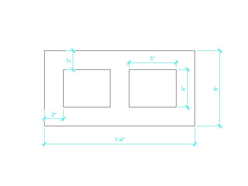
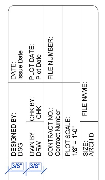
Make modifications
as demonstrated in class including modifying the portions of the title
block as shown below. The lettering in this portion of the Titleblock
are both Text and Labels at 3/32". Dimensions shown
are for your reference and are the spacing between the lines shown.
Do not include these dimensions on your Titleblock.
-
Design
a logo of your choosing as instructed below.
Include a company name, address,
phone number and website address below, nearby or included in your logo.
See image below:
-
Logo
Design a logo for your Titleblock.
Choose a name and style that fits your career ambitions or personality.
You may design something in Revit, AutoCAD or another image program.
Use the following criteria:
Your logo must be unique
An image file or CAD file
Inserted where the Revit logo
is on the Title block template
Does not have to look 3D
Include your name or a company
name
Include some graphical styling
Consider some design
ideas that you can find on the web. Below are some images of some
AutoCAD files of logos from some companies that I have worked with in the
past. Also check out my previous class for previous student logo
designs at:
http://edandi.com/Instruction/2010-4-IET-161/
-
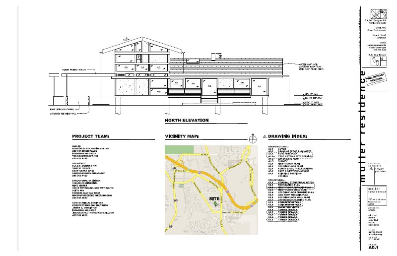
Examples of some cover sheets
with logos.
-
Another sample project of
a house to be built in Issaquah.
-
Floor plan example with
wall, door, window and room tags with the associated schedules.
-
-
-
Week
9:
Design
Assignment due: For
your ICE (In Class Evaluation) on Tuesday you will be required to complete
2 items:
Download
the Revit model at the link as instructed in class and incorporate the
various items listed below
Progress
on your Commercial Project including sheet items with a modified Titleblock.
Read
and practice ahead:
Your
Revit textbook, Chapters 11 and 18. Read and practice these before
class on Thursday.
Class
exercises and assignment details: More details later.
In Class Evaluation (2 items)
Click
here for your Week 9 ICE grading criteria.
Download and complete the Revit model (similar to last week's) at the link
given in class. Show progress on your Commercial Project per the
guidance below including your sheet family embedded in your Commercial
Project. You will have 45 minutes to complete these items.
At the end of the evaluation, hand in these 2 items in one folder with
your name in it at the instructor's computer. At the same time, print
out, sign and hand in your ICE Grading Criteria.
Download
the Revit model at the link given in class and incorporate the following
items as demonstrated in class or as read and understood from the textbook.
Week 9 Revit Model (coming before Tuesday's ICE). You will have 45 minutes
to complete it. 30 points total.
Furniture
Line up
the desk to the nearby wall in the reception area
Load and
install furniture tags on the installed items
1/4" leader,
neat and legible
Create
a furniture schedule
Use the
following fields in CAPITALS in order from left to right: Type Mark, Family
and Type, Manufacturer, Count, Cost
Fill in
all blank fields, center and sort Type Mark field (ascending), on appearance
tab uncheck Blank row before data"
Windows
Modify
the following window heights
Install
window tags, no leaders, neat and legible
Create
a window schedule
Use the
following fields in CAPITALS in order from left to right: Type Mark, Family
and Type, Manufacturer, Width, Height, Level, Count, Cost
Fill in
all blank fields, center and sort Type Mark field (ascending), on appearance
tab uncheck Blank row before data"
Doors
Modify
the following door locations
Install
door tags, no leaders, neat and legible
Create
a door schedule
Use the
following fields in CAPITALS in order from left to right: Mark, Type Mark,
Family and Type, Manufacturer, Width, Height, Level, Count, Cost
Fill in
all blank fields, center and sort Type Mark field (ascending), on appearance
tab uncheck Blank row before data"
Incorporate your sheet family
into the ICE project with the updated title block from Week 8
Title block
Width adjustments as done in
class
Cell adjustments as demonstrated
in class.
Text sizes, properly named
Logo as described in the Week
8 section above
Incorporate into your ICE, proper
fields filled in
Create
a first floor plan sheet
Sheet name: "GROUND FLOOR PLAN",
Sheet number "A-1"
Insert Ground Floor onto sheet
CAPITALS, center left alignment
for the view
Hidden line visibility for the
view
Crop and hide area
Scale, 1/4" = 1'-0"
Adjust the view title to just
below the view and dimensions, aligned on the left side of the building
Modify and incorporate your
ROOM SCHEDULE to the lower right of the Ground Floor plan
Progress on your Commercial
Project.
Show exterior walls and dimensions
Permanent dimensions in whole
or half foot increments, all external wall features, no redundant dimensions
Dimensioned from the exterior
wall edges
Show custom levels, CAPITALS
Room bounding with consecutive
numbers and names in CAPITALS
Interior walls and dimensions
(custom or developed in Week 4), at least 10
Connected and trimmed
From the one level to the next
level
Permanent dimensions in whole
foot or inch increments, at least 10
Dimensioned from a common wall
edge as shown, to the centerline of the interior walls
Floors, at least 2 (library,
custom or developed in Week 5)
Exterior doors, at least 2,
double door for large facilities
Interior room doors with trim
at 30"
Stairs if appropriate
48" wide at least
Edit profile of floor to cut
out area for stairs and railings
Create a sheet for the Ground
Floor plan
Incorporate your sheet family
into your Commercial Project with the updated title block from Week 8 with
the proper fields fill in
Insert your ground floor onto
this sheet
CAPITALS, center view
Proper scale
Hidden line visibility for the
view
Crop and hide area
Adjust the view title to just
below the view and dimensions, aligned on the left side of the building
Out of
class instruction:
The following are videos
demonstrating various detailing and drafting options available in Revit
Architecture. Click on the following link: Week
9 Instructional Videos, click here
-
-
Week
10:
Design
Assignment due: Your
second midterm exam will be on Tuesday. See details below.
Read
and practice ahead:
Work
on your Commercial Project.
Class
exercises and assignment details:
Your
second examination will be on Tuesday. To prepare for the written
portion of the exam you need to be certain that you have read and practiced
all of your reading assignments and have studied your notes taken in class.
For those that read the website, the following is information that will
be included in an exam question: Know and be able to order the elements
of a Revit family tree.
For
the design portion of the exam you will be modeling a commercial
building like a small restaurant and will incorporate
many of the design elements that have been demonstrated in class.
Practice and be able to demonstrate the following items as described below.
You may create a new project prior to the exam and use it for the exam
incorporating many the items listed below.
Scale, make the floor plan scaled
at 1/4=1-0, set your units to a precision of 1/2" for length
Levels, create, modify and name
5 levels in CAPITALS:
Floor plans for the Floor and
the Roof
Exterior walls, create a single
story building with walls from the Floor to the Exterior Wall level. Location
Line on the Core Face Exterior
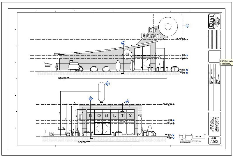
Create an elevation of the angled
wall and name it NORTH WEST
Wall type, custom per the following
guidelines, name this wall:
Metal stud structure, 5-1/2
and more, second finish with paint, color of your choice, extra credit
for a parapet top
Site, Toposurface with a 0
elevation around the building and down to -5 in the back of the building
only about a building width around all sides, building pad, parking lot,
apply materials
Floors, Insert a custom floor
for the Main Floor no flashing floors
Interior walls, custom per the
following guidelines, name this wall including the name of the wall color:
Wood stud structure, 3 1/2
and more, second finish with paint color of your choice (same as the interior
of your exterior wall), height offset 12 from the roof level.
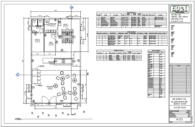
Rooms, rooms bound and labeled
with the following names in CAPITALS: Customer Area, Service Area, Storage,
Preparation, Office, Mens Room, Womens Room, locations of your choosing,
counter wall to the Server level. Provide angled or curved walls.
Restrooms in the south east
corner, doors on the north wall, behind a 3 screen wall both rooms 11
x 10
Dimension all walls from exterior
wall to center line of interior wall
Ceilings, insert ceilings for
the Floor 2 x 2 ACT System at 12 6 in the Customer and Service areas,
Insert Troffer lights, Parabolic,
12 at least in the Customer and Service Areas, align these
Store Front Curtain walls, on
two sides - north and east adjoining each other, 6" from Floor to 12 horizontal
spacing, 7 vertical spacing 4
Doors, Insert the following
doors with tags.
Provide an archway opening from
the Preparation Area to the Service Area, 60
Provide a door or archway from
the Service Area to the Customer Area.
Window, Awning with Trim for
the drive up window with tag, 60 wide, 36" tall, sill height 2 6
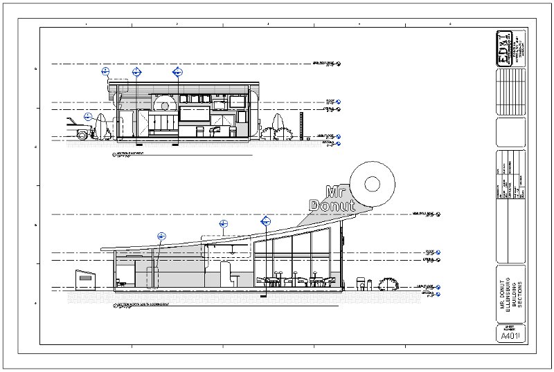
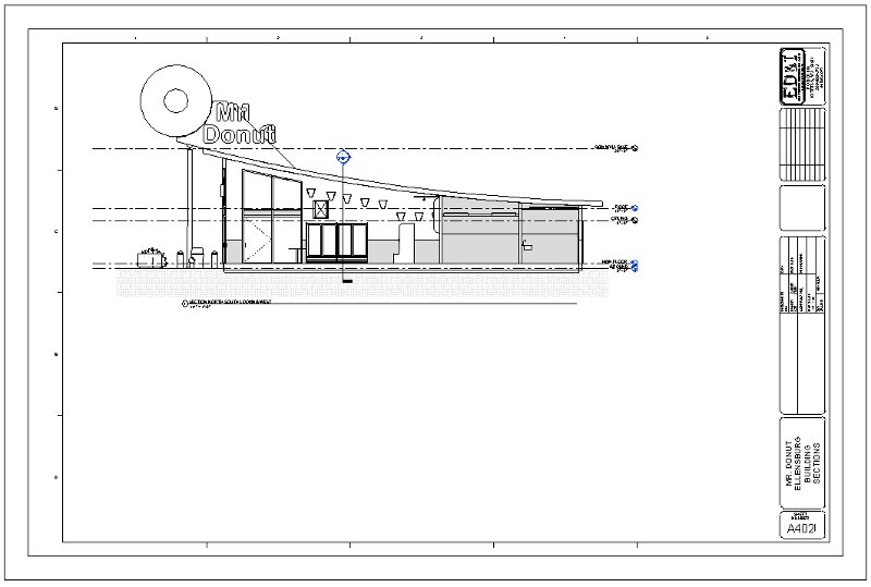
Add 2 building sections perpendicular
to each other.
Roof, from the Roof level, no
slope, on the interior side of the exterior wall, Steel Truss - Insulation
on Metal Deck EPDM
Make the roof slope to the edges
with a high point in the center at 6
Components, insert from the
Autodesk "Seek" website: counter top-island, pastry, showcase, donut, grocery,
pastry, case, cash register or similar display item for your store for
the display of various items. Place some of these within your counter
wall, 6 minimum.
Schedules, create a room schedule
with the following fields, in CAPITALS, in the order listed: Number, Name,
Perimeter, Area, Base Finish, Floor Finish, Wall Finish, Ceiling Finish.
Number column is centered, fill in all fields, like we did in class.
Sheet, Create a Floor Plan sheet
of the Floor, number it 105, name it FLOOR PLAN
Logo per Week 8,
Fill out the rest of the Title
Block with the appropriate information
Insert the Room Schedule on
the right
Line up view titles
Print it out at 1/2 size (as
instructed)
Render, low resolution, of a
camera view from the Customer area looking at your counter, eye level at
2, sun and artificial lights, save to project, name this
No more information to follow
-
-
Week
11:
Design
Assignment due: For your ICE (In Class Evaluation)
on Tuesday you will be required to complete 3 items:
Use the
Revit model as instructed in class and incorporate the various items listed
below regarding details and sheets.
Progress
on your Commercial Project including setting up sheets.
Rendered
images of the inside of your project.
Design Assignment
due: Decide on the Revit toolbar or function
that you would like to demonstrate during your Final Commercial Project
presentation. See guidelines and examples below.
Read
and practice ahead:
On Thursday,
be prepared to discuss your toolbar or function that you will demonstrate
for your Final Project presentation, this will be graded.
Class
exercises and assignment details:
In Class Evaluation (3 items)
Click
here for your Week 11 ICE grading criteria.
Modify your Exam 2 model. Show progress on your Commercial Project
per the guidance below. Complete various rendered images of your
project both inside and out. You will have 45 minutes to complete these
items. At the end of the evaluation, hand in these items in one folder
with your name in it at the instructor's computer. At the same time,
print out, sign and hand in your ICE Grading Criteria and the required
sheets from your Commercial Project on 11" x 17" paper.
Complete
and modify your Revit model from Exam 2. Make certain your exterior
wall is the Exterior-5-1/2 EIFS-Metal-GWB type. Incorporate the
following items: (30 points total)
Insert
two building sections both east-west (facing south) and north-south (facing
west), name these as such
Adjust
length units to The Nearest 1/4 precision
Insert
a detail Callout in the north-south section of an exterior wall (the lower
5 feet of the wall)
Rename
this detail in CAPITALS, Detail-Exterior Wall, move the balloon to the
exterior of the wall
Scale
1 = 1-0
Install
Break Line Detail Components on the top of the wall and on the sides and
bottom (show the 6 slab and about 2 feet of space below)
Organize,
order and line these up (aligned on the center of the walls)
Install
Metal Stud Detail Components as a C stud section of the appropriate size
from the Structural Metal Studs Framing folder
Double
base plate with open ends of the studs facing each other
Single
stud, open end down, 4 0.75 from the Floor level, dimension this
Install
insulation of the appropriate width up to the stud section and again on
top of it, re-order Detail Components if needed
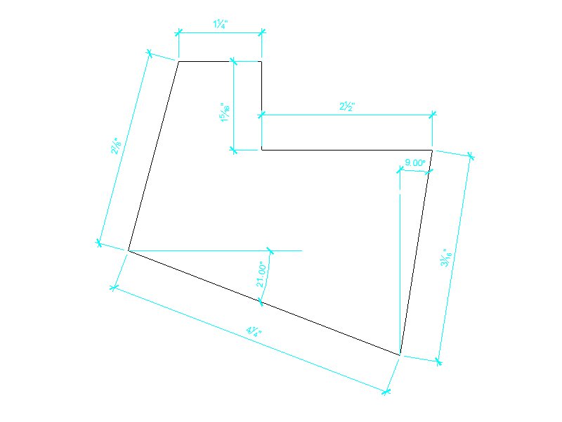
Fill a
region covering the concrete slab by creating a footing on the edge of
the wall, use Wide Lines sketch lines, create a new hatch pattern for the
concrete (from the existing Fill Patterns library), make the footing shape
per the dimensions in the image provided
Fill the
Earth up to the edge of the footing using a method similar to above
Create
a region of compacted earth under the footing and slab using the Sand Dense
pattern
Install
a Metal J bolt Anchor Bolts Hook-Side from the 050500-Common Work
Results for Metals folder for the bottom of the wall, J size 4, make
the depth as shown in the image provided, line up washer with the bottom
of the studs
Insert
text callouts with dog leg leaders and dimensions as shown in the image
provided
Insert
a new sheet with your sheet template, updated titleblock
Number
401, name in CAPITALS called Details, insert this detail
Progress
on your Commercial Project (30 points total)
Show exterior
walls, permanent dimensions in whole or half foot increments, all external
wall features, no redundant dimensions, dimensioned from the exterior wall
edges
Insert
two perpendicular building sections, rename to a descriptive name
Interior
walls and dimensions, permanent dimensions in whole foot or inch increments,
at least 10, dimensioned from a common wall edge to the centerline of the
interior walls
Create
a sheet for your Ground Floor plan, number A101, descriptive name of your
choice in CAPITALS
Incorporate
your sheet family into your project with the updated title block
Insert
your ground floor onto this sheet, CAPITALS, center view
Proper
scale, hidden line visibility for the view, crop and hide area
Adjust
the view title to just below the view and dimensions, aligned on the left
side of the building
Create
and insert a Room Schedule using guidelines from previous weeks
Create
a detail callout and sheet similar to above
Print
two sheets, ANSI B, 11x17
Provide
2 low resolution renderings of interior of your building, artificial and
sunlight settings, proper exposure (adjust settings and surface finishes
to achieve a decent look)
Non default
settings
Toolbar or Function presentation
guidelines Decide on a toolbar
or function that you would like to demonstrate to the class during your
Final Commercial Project presentation. Discuss this during the class
period on Thursday. Plan on spending between about 2 to 4 minutes
demonstrating this toolbar or function during your project presentation.
Examples include, but are not limited to, the following. The selection
of a toolbar or function will be a graded item for this week:
Various
BIM features like parameter interfaces involving sheets
Various
BIM features for use in scheduling and estimating
Additional
options for enhancing Walk Throughs
Breaklines
and methods for breaking up large projects to fit on sheets
Various
options for creating a logo and in 3D
Additional
functionality and items to schedules
How to
modify families including the use of planes
Modifications
and additional options in modifying families like curtain walls, doors
and windows
Additional
wall family options like stacked walls and adding paint, sweeps and reveals
Using
a material takeoff schedule
Managing
and creating materials
Pick a
tool, any tool, and explore
Out of
class instruction:
The following are videos
demonstrating various additional items discussed in class such as the "Paint"
tool and Drawing Sheet update options.
Click on the following link:
Week
11 Instructional Videos, click here
-
-
Final:
Design
Assignment due: Your
model and a sheet set per the instructions below. The instructions
below have been updated, no further additions will be made. A grading
criteria has been posted below.
Read
and practice ahead:
The book,
if you have not read it yet.
Problem
Printer Solutions:
Below is a solution
for some of the printing problems in the lab.
Regarding images being flipped
or missing on the plotter and printer, use the following procedure:
Create a pdf document instead,
using the print command.
Instead of printing to one of
the three lab printers choose the cutepdf printer.
Go to the Printer properties
button and select the ARCH D paper size
Pick a file save location in
your Commercial Project folder
Your standard 36" x 24" sheet
should now be generated as a 36" x 24" sized pdf document
Open the folder where this pdf
is and open the file. Print this using the HP6015 printer or the
HP800 plotter.
For the HP800 click on the printer
Properties button
Check the "Autorotate" button
Select the roll size of 24"
Start printing and if its not
right go to the plotter and "cancel" it, check and change your settings
and start again.
Regarding getting your sheet
to fill up the page or printing to full scale on the plotter. Or
the plotter does not recognize the ARCH D sized paper.
Below is a new procedure
for printing full size sheets in Revit Architecture on the HP800 plotter
The items listed below are
from the website, items with the strike through are replaced by an alternative
method:
To print on the HP800 plotter,
choose the following settings
Put in the 24" sized paper roll
Through Revit,
Choose ARCH "D" size
Create, instead, a custom size 36 x 24 sheet size
Click Setup button
Choose, Center, Landscape, Zoom
to 100%
Click the printer Properties
button
Check the "Autorotate" button
Select the roll size of 24"
Start printing and if its not
right go to the plotter and "cancel" it, check and change your settings
and start again.
Measure your Graphic Scale
Bar
Your Commercial Project will
have the following items included in a sheet set as described below.
Make certain that you understand your markups and incorporate the corrections
into your Final Project drawings.
Sheets
Number them in ascending order
Incorporate all of the elements
for these sheets as required from the previous weeks' assignments including
Titleblock items. Title block items also include fields filled in
from your Project Information and your Sheet Properties (see videos above).
General sections are often numbered
similar to the following
Cover Sheet, no number, 000,
001
Site Plan 010 series
Floor Plans 100 series
Ceiling Plans 200 series
Elevations 300 series
Sections 400 series
Schedules and/or Legends 500
series
Details 600 series
Notes:
Legends and schedules may be
included on other relevant sheets if there is room.
If a sheet series is blank then
move up the numbering to maintain the sequence.
Extra credit for extra effort
and items, and may include, sheet notes that better explain elements of
your project, extra schedules, legends and similar items.
See some sheet examples at the
end of this section.
Titleblock
Logo, company name and address,
orientation, size (extra credit for more items)
Fields lined up, information
filled in
All text that you control CAPITALized
Cover Sheet
All text that you control CAPITALized
Project title
Project sub title
Project address
Project team members
Image rendering of the exterior
of the proposed project
Map of the project site with
title
Sheet list with title
Fields include, Sheet Number,
Sheet Name, Designed By, Drawn By, Checked By, Approved By
Center all fields except the
Sheet Name
Use requirements from previous
schedules
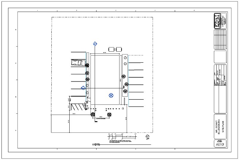
Site Plan
Hidden line visibility for view
View is cropped and crop boundary
hidden
View title orientation
North Arrow (extra credit for
a modified or unique one)
Rotate the arrow off center,
consistent orientation and location on all plan sheets
Graphic Scale Bar, choose the
correct size (extra credit for a modified or unique one)
Hide your building to reveal
your Building Pad (don't show the building)
Hide other non relevant non
site plan building features
Property line
Show dimensions from property
line to the building pad
Show other relevant dimensions
All text that you control CAPITALized
Floor Plan, include the following
from the list below. If the items in the list do not fit on the floor
plan sheet then move them to a Schedules or Legends sheet. The items
listed below are in order of importance so move the bottom items first
to the new sheet. Keep the Door, Window and Wall Schedules together.
Plan fills sheet, centered
View is cropped and crop boundary
hidden
View title orientation
North Arrow
Graphic Scale Bar
Hidden line visibility
Dimensions (use previous requirements)
Tags for doors, windows and
walls, organized
All text that you control CAPITALized
Door Legend for plan symbols
(see videos above)
Window Legend for plan symbols
(see videos above)
Room Schedule (use previous
requirements)
Door Schedule (use previous
requirements)
Window Schedule (use previous
requirements)
Wall Schedule (use the following
fields: Type Mark, Family and Type, Fire Rating (list in hours), Length,
Width, Area (order and center the Mark field)
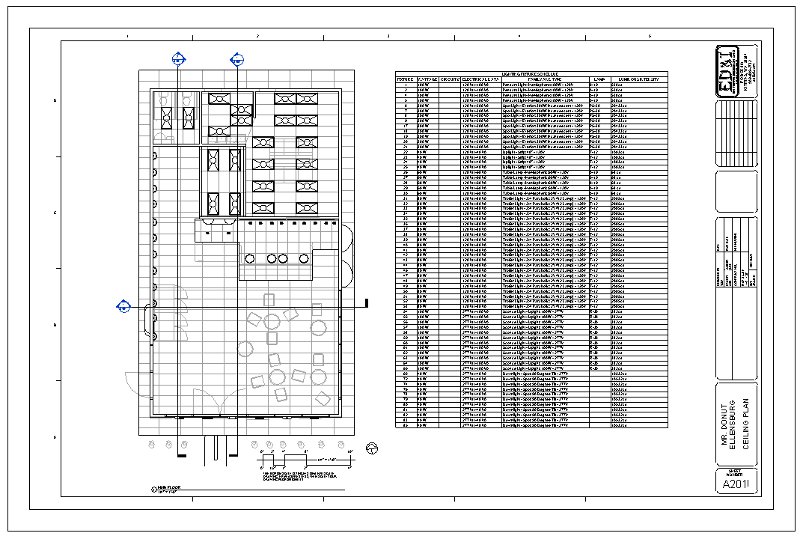
Reflected Ceiling Plan (if you
have a suspended ceiling, otherwise a modified floor with a ceiling will
be graded)
Hidden line visibility
View is cropped and crop boundary
hidden
View title orientation
North Arrow
Graphic Scale Bar
Lighting Fixture Schedule with
the following fields in order: Fixture (Mark), Wattage, Circuit # (leave
this blank), Electrical Data, Family and Type, Lamp, Luminous Intensity
Center the Fixture (Mark) column
Use a new sheet(s) if you need
more room, name the sheet "Lighting Fixture Schedule"
All text that you control CAPITALized
Elevations, 2 or 4 sheets
Hidden line visibility
All views cropped and crop boundary
hidden
View title orientation
Elevation relevant dimensions
only, include all that apply
Graphic Scale Bar
Door Legend for elevations
Window Legend for elevations
Sections, 1 or 2 sheets
Hidden line visibility
All views cropped and crop boundary
hidden
View title orientation
Section relevant dimensions,
include all that apply
Graphic Scale Bar
All text that you control CAPITALized
Schedules/Legends
If not included on other sheets
List in order per the sheet
numbering sequence listed above
Incorporate all of the elements
required this quarter
All text that you control CAPITALized
Details
Hidden line visibility
All views cropped and crop boundary
hidden
Smaller scale than the parent
view (1" = 1'-0", 1/2" = 1'-0", etc...)
Provide at least 6 details similar
to what has been done in class
Have at least 5 annotation elements
such as callouts and dimensions per detail
Must have annotation callouts
with dog leg leaders
3/32" text size, Arial, CAPITAL
lettering
Insert break lines
Show examples of a 2D filled
regions
One section detail of an exterior
wall with insulation
One section detail of an interior
wall with a fire stop
All text that you control CAPITALized
Print your sheets, have these
printed before the Final on Tuesday! or points off in a big way
Print out all sheets 1/2 size
(11" x 17" ANSI B size)
Staple or fasten in upper left
corner
Print out 3 full size sheets,
in color
Cover sheet, first floor plan
and one of your elevations or section sheets (choose the one with more
detail)
Print on the HP800 plotter,
choose the following settings
Put in the 24" sized paper roll
Through Revit,
Choose ARCH "D" size
Click Setup button
Choose, Center, Landscape, Zoom
to 100%
Click Properties button
Check the "Autorotate" button
Select the roll size of 24"
Start printing and if its not
right go to the plotter and "cancel" it, check and change your settings
and start again.
Measure your Graphic Scale Bar
Call or email if problems
Toolbar Demonstration grading
criteria:
Name the the toolbar or function
Demonstrate the tool(s) or function(s)
Demonstrate the steps involved
Demonstrate different options
Demonstrate the effects of the
different options
You will graded on the quantity
of the steps and/or options demonstrated (at least 8)
Project Presentation, as evaluated
by your peers:
Commercial Project
presentations on Tuesday. You may use the following guidelines or
something similar for your presentations:
Introduction, provide your name,
major and class position (senior, junior, etc...)
Introduction to your project,
project name and service provided
Tour
Start with a 3D view, the floor
plan or other view. Since these are all commercial projects your
design should be facilitating the interaction between customers and staff,
explain and demonstrate this
Show how a customer will approach
the building (street and parking)
Show how a customer will enter
the building and interact with staff
Show and explain the service
area
Show the support areas
Show auxiliary areas
Move on through the model and
demonstrate any features that you think are significant in your project
that may not be apparent in other student projects or that have not been
demonstrated in class
Show elevations, sections, 3D
view, camera views and/or renderings of any features that you feel help
demonstrate how your building functions and the features associated with
that function
Show the more significant components
used and where they came from
Show a brief Walk Through, 1
minute maximum with narration
Describe a toolbar, function
or modeling technique unique to what has been demonstrated in class and
that you have applied to your project.
Conclusion:
Summary
Ask for questions
Ask for suggestions i.e. "how
can I model this differently or better"
I would invite interaction and
would encourage raising your hand to interrupt for explanation or to share
a different technique.
Keep your presentation to around
7 minutes, practice this! Points taken off for over or under this
time.
Evaluation feedback forms
will be handed out at the beginning of the class and include the following
criteria:
Sign your name on the cover
only
Fill in the student's name,
on each page in the book, in the space provided
Provide suggestions and constructive
comments (points off for a blank page)
Provide a fair evaluation on
your peers projects based on the listed criteria. Circle the number
that you feel best describes your peer's placement in each evaluation section.
Complexity and Effort:
How complex or how much effort do you think this student put into the project
(consider the number of elements and the quality of the details apparent
in the model)?
Comments: A lot of effort,
Average amount, Needs more effort, Very little
effort
-
Design Quality and Completeness:
(does it look attractive, does it look like the real thing, is it put together
correctly, does it work for its intended function, is it complete?
Toolbar and tool demonstration
(did the student demonstrate all of the tools or functions, will you be
able to use this tool or function after this demonstration, did you learn
something about these tools?
Comments: Very informative,
Mostly complete, Could have shown more, Learned little
-
Presentation (spoken clearly,
easily understood, organized, did it take too long, explained project?
Comments:
Great job, Very good,
Average, Needed better preparation
and rehearsal
-
Overall Impression of the project
and presentation:
Comments:
Great job Good job Average
Needs work Incomplete
The item(s) that I feel need(s)
more work are:
The best thing about this
project is:
Project Design grading criteria:
May include everything we have covered in Revit this quarter.
Custom levels, renamed in CAPITALS
Custom walls, one exterior,
one interior, rename these with the word "Custom" preceding the name
Custom floor, rename this with
the word "Custom" preceding the name
Appropriate number of windows
and doors at consistent heights and symmetry
Rooms and room bounding for
all internal areas.
The following three categories
will be counted and totaled for a single grade. This allows someone
with a very large project with many walls, floors, ceilings, windows and
doors to be judged with a smaller project that has many more components.
Walls, floors, roofs, ceilings,
doors and windows will be counted, repeating items such as windows may
be counted less, expecting about 40 items
Components will be counted,
these will include exterior and interior items, they may include items
such as lights, equipment, plumbing fixtures, furniture and similar items,
repeating items such as ceiling lights may be counted less, expecting about
50 items
Site plan components such as
contours, subregions, parking, landscaping and similar items, repeating
items such as plants and lights may be counted less, expecting about 30
items
Sample Sheet Set
-
-
-
DESIGN
GALLERY
A collection
of the exceptional work demonstrated
by
this class.
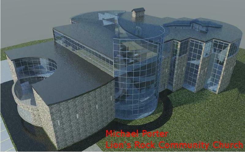
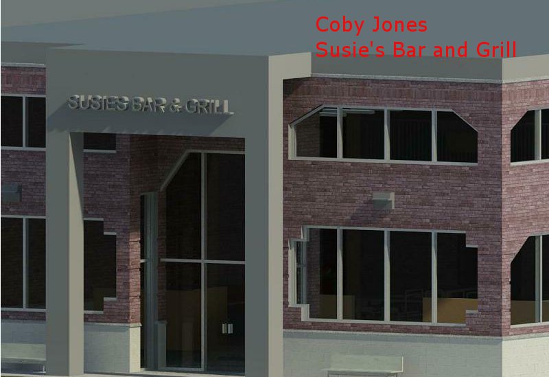
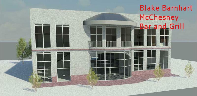
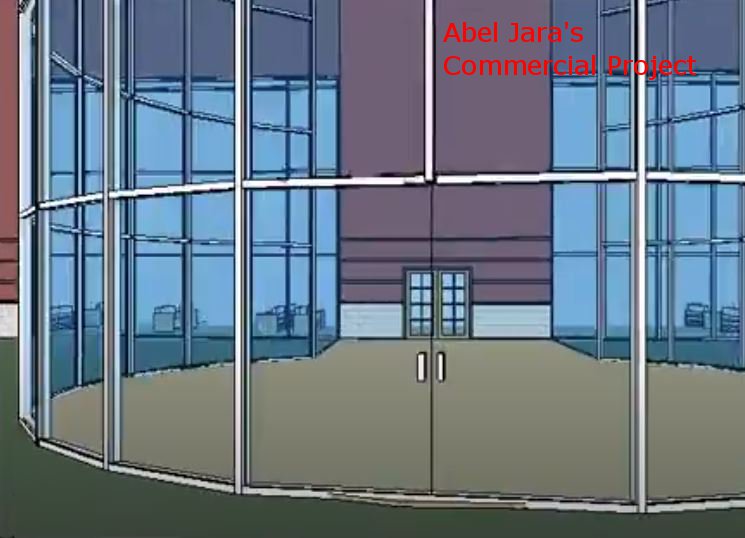
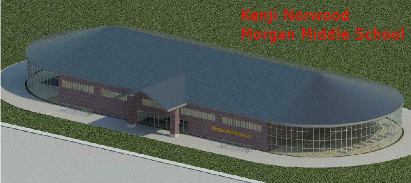
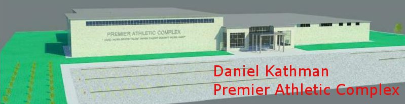
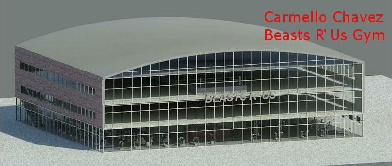
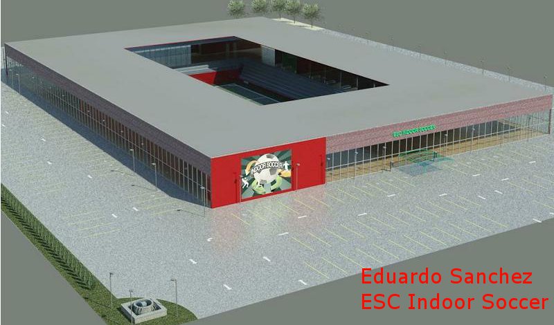
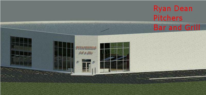
The
first set of images are from the students Final Project featuring a Commercial
Building Project. The student with the highest ranking, as evaluated
by their peers during their project presentations was Michael Porter and
his Lion's Rock Community Church design. Following close behind was
Micah Thompson, Jon Klemkow, Coby Jones, Blake Barnhart and Abel Jara.
View
images of their work below. Click on the images for "Walk Through"
videos.
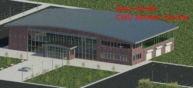
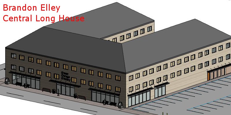
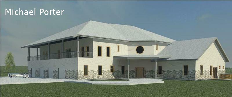
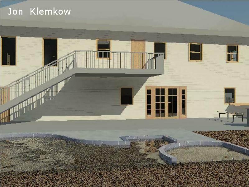
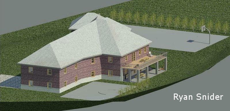
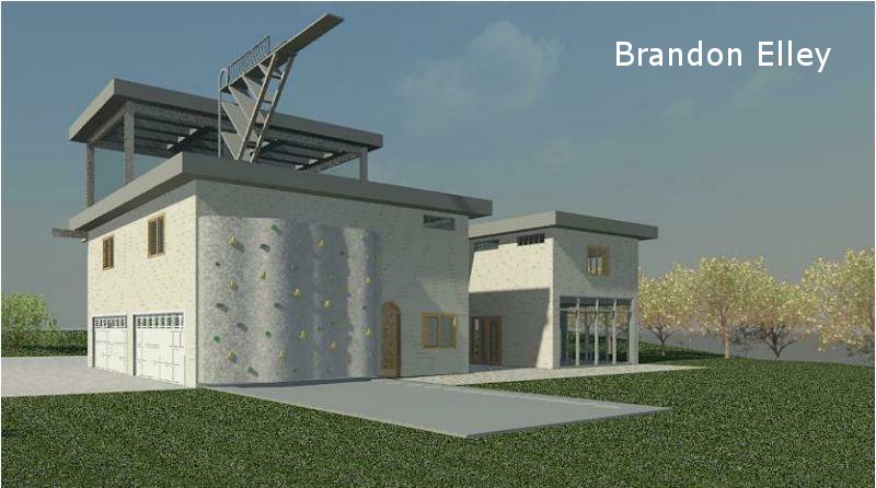
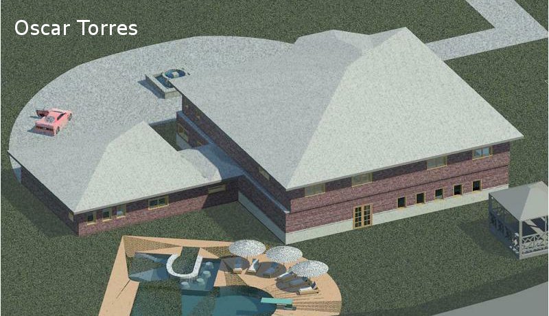
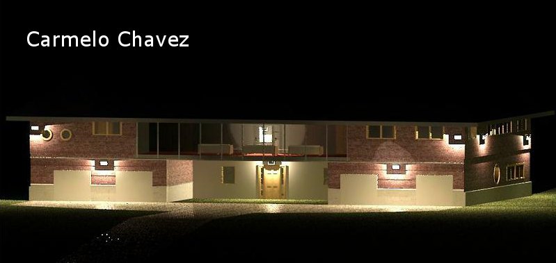
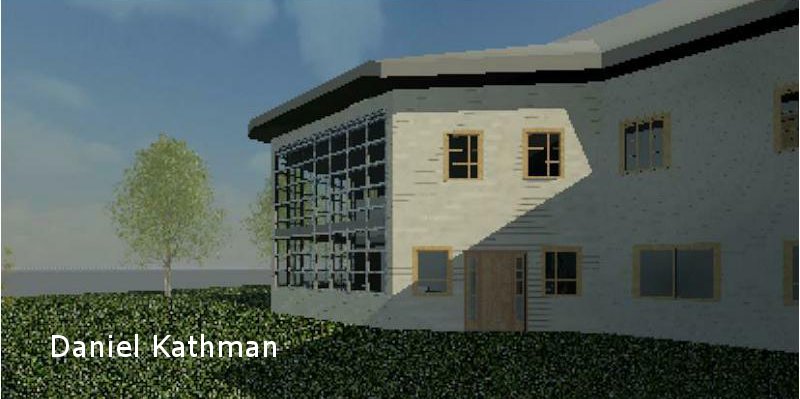
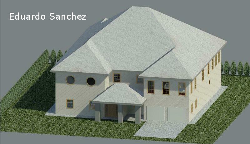
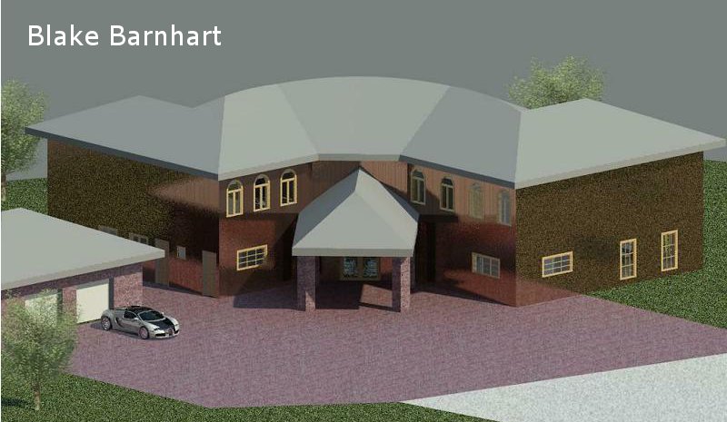
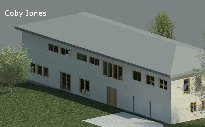
The
following set of images are from the students Dream House design.
The student with the highest ranking, as evaluated by their peers during
their project presentations was Michael Porter followed by Philip O'Leary,
Jon Klemkow, Ryan Snider, Abel Jara and Brandon Elley.
View
images of their work below. Click on the images for "Walk Through"
videos.