|
- |
|
|
 |
 |
-
| Week
1:
Design
Assignments due this week:
None
this week but come to the first class of Week 2 prepared by starting the
Design Assignments listed in this section below and in the Week 2 section
following.
Announcements:
Please
purchase download or otherwise acquire the following books listed below
for use in this class:
Engineering
Design... (ED)
oooo
Available
at the bookstore oooooooooooo
|
The
Ultimate GD&T Pocket Guide (UG)
Available
at the bookstore
ooooo |
Student's
Guide...
(SG)

Available
on the Student Resources page
|
d
Read
and practice ahead:
Begin
reading the engineering design book (ED) beginning with the introduction.
Then start with Project 1 designing the Plate following the steps
involved. Continue on with the Rod and the Guide.
Begin
reading the student guide (SG) from the introduction through Lesson 1 then
design the Box in Lesson 2 following the steps involved.
There
will be an evaluation on the first day of class next on these assignments.
|
In
Class exercises and assignment details:
-
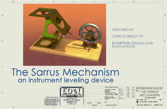
The Sarrus Mechanism Demonstration
click on the following link
for a zip file of the parts and assembly Sarrus
click on the following links
for pdfs of the part drawings.
Base
Plate
Hinge
Push
Rod / Pin
Wheel
Wheel
Mount
Out of
Class Design Assignment details:
-
ED Book
-
Start the Plate in Project
1
-
Create the various part template
files (see the video links below)
-
SG book, Lesson 2
-
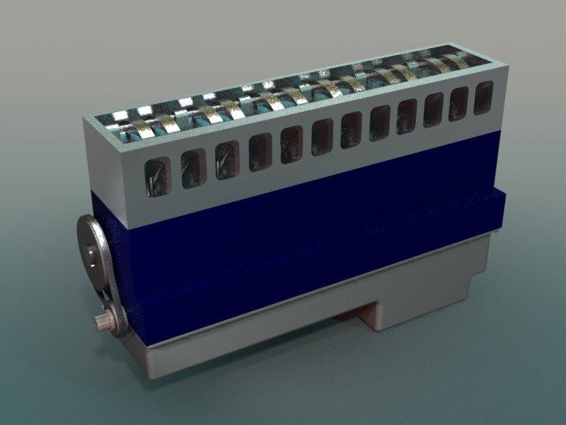
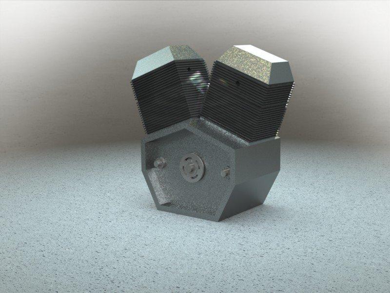
VD the Junction Box video,
see
links below.
Instructional
Videos:
-
View this
week's Instructional Videos at this links on the listed subjects below:
1.
Getting Started, Part 1, Creating the MM SolidWorks Part Template File
2.
Getting Started, Part 2, Modifying the MM Template File for the Inch Part
Template File
3.
Getting Started, Part 3, Junction Box, The Feature Manager
4.
Getting Started, Part 4, Junction Box, Sketching for 3D Features
5.
Getting Started, Part 5, Junction Box, Sketching for Creating Holes
6.
Getting Started, Part 6, Junction Box, Extruded Cut for Side Holes
7.
Getting Started, Part 7, Junction Box, The Fillet and Shell Features
8.
Getting Started, Part 8, Junction Box, The Hole Wizard and Finishing the
Model
|
- |
|
|
 |
|
-
| Week
2:
On the
first day of class this week come to class with the completed assignments
from Week 1 in preparation for your In Class Evaluation (ICE). See
details below. |
In
Class exercises and assignment details:
-
In Class Evaluation (ICE) (2
items). Click here for your Week
2 ICE Evaluation Check List, print this out, fill in the needed information,
follow the instructions and hand it in at the end of the evaluation at
the instructor's desk. On the first day of class this week we will have
an evaluation of the models completed so far from Week 1, the Plate,
Box and Junction Box. The evaluation criteria will include:
-
Junction Box (10pts)
-
Completeness with symmetry (2pts)
-
Fully defined sketches with
dimensions (3pts)
-
Orientation (1pt)
-
Extrude, Feature Fillet, Shell,
Extrude Cut for hole (1pt each)
-
Extras and errors
-
Press Plate (10pts) similar
to the Plate in the ED book
-
Units millimeters, Material,
AISI 304 Steel, base sketch on Front Plane
-
Completeness with symmetry,
origin and planes are in the center (2pts)
-
Correct starting plane (1pt)
-
Fully defined sketch with dimensions
(2pts)
-
Rename your Extrude Boss/Base
to Base Cut Extrude to Front Holes (2pts)
-
Extrude, Feature Fillet, Extrude
Cut for holes (1pt each)
-
Mass (2pts)
-
Extras and errors
Out of
Class Design Assignment details:
-
Complete the Plate, start
the Rod and
Guide
in Lesson 1
-
The exercises from the end of
Project 1 on the Class Schedule
SG book, Lesson 2
The Section videos referencing
the ED book exercises below
Instructional
Videos:
-
View this
week's Instructional Videos at this links on the listed subjects below:
9.
The "T-Section", Version 1, Sketching Half then Using the Mirror Command
10.
The "T-Section", Version 2, Sketching, Offsetting and Trimming
13.
Understanding Sketch Element Line Colors and Sketch Relations
150.
Getting Started, Switch Plate-1, Showing and Overview of Various Features
151.
Getting Started, Switch Plate-2, Sketches, Center Rectangle, Centerlines,
Geometry, Relations
152.
Getting Started, Switch Plate-3, Chamfer, Extrude Cut, Hole Wizard with
Various Options
153.
Getting Started, Switch Plate-4, Applying the Shell and Rib Features with
Various Options
154.
Getting Started, Switch Plate-5, One Sketch that Drives them All and the
Contour Select Tool
|
- |
|
|
 |
|
-
| Week
3:
On the
first day of class this week come to class with the completed assignments
through Week 2 in preparation for your In Class Evaluation (ICE).
See details below.
A new
video has been added below. |
In
Class exercises and assignment details:
-
In Class Evaluation (ICE) (3.5
items). Click here for your Week
3 ICE Evaluation Check List, print this out, fill in the needed information,
follow the instructions and hand it in at the end of the evaluation at
the instructor's desk. On the first day of class this week we will have
an evaluation of the models completed so far through Week 2. The evaluation
criteria may include:
-
The Square Tubing refer
to the image (in class) (10 pts)
-
Completeness with symmetry (1pt)
-
Correct starting plane (1pt)
-
Material 6061-T6 (SS) (1pt)
-
Fully defined sketches with
dimensions (1pt)
-
Feature or Sketch Fillet, End
Cut, Holes (1pt each)
-
Find the Mass, precision at
3 units after the decimal (3pts)
-
Extras and errors
-
Mystery Part 1 (from last week)
(10pts)
-
Correct starting plane (1pt),
material (1pt)
-
Fully defined sketches with
dimensions (2pts)
-
Proper dimension values (2pts)
-
Mass, precision at 4 units after
the decimal (2pts) Center of Mass x, y and z (2pts)
-
Mystery Part 1 (from last week)
modified (10pts)
-
Rename this model, keep the
original (1pt)
-
Modify model: total height 2.25,
total width 3.5, width top step 1, depth 2.5, height bottom step 7/8,
Mid Plane Extrusion (3pts)
-
Mass, precision at 4 units after
the decimal (3pts) Center of Mass x, y and z (3pts)
-
Extras and errors
-
Mystery Part 2 (10pts)
-
Completeness with symmetry (1pt)
-
Rename your features (1pt)
-
Correct starting plane (1pt)
-
Material TBA (1pt)
-
Fully defined sketches with
dimensions (2pts)
-
Features (4pts)
-
Extras and errors
Out of
Class Design Assignment details:
-
Assembly Models. On Wednesday
we will discuss what you propose to model or this project per the detailed
criteria below. You need to explain what you will call your model
(such as Bar-B-Que, video game controller, socket ratchet handle, conveyor
belt, car, bike or similar items), what it is to be used for, how it will
work then describe each of the different part components and how they will
interact with the assembly. We will discuss these ideas as a class
and I will provide some guidance on how to get started using various modeling
techniques. Assignment details follow:
-
Design at least 3 unique parts
with the expectation of assembling them for the next Design Assignment.
Parts in the assembly, other than the base, must be able to move, rotationally
or translationally (like a machine). Think of the Sarrus Mechanism.
-
Parts (3 total including the
Base), include the usual criteria for evaluation
-
Base, one part has to be a base
feature to be fixed to the Origin in the assembly.
-
To have a round or rectangular
hole(s) or slot(s) or an extruded boss(es) for use as a reference for the
insertion of additional parts
-
Hole Wizard holes in the base
for mounting to some external structure
-
Parts2 and 3 (or more)
-
To be inserted on the base or
on one of the other parts
-
Must fit into the slots, holes
or bosses on the Base as described above
-
Fasteners, connectors, pins
and similar items are not appropriate parts for this assignment but can
be used.
-
Include the following features
on at least one of the parts above:
-
Hole Wizard feature on a part
other than the Base
-
Linear or circular pattern
-
Include a Fastener from the
Toolbox in the Design Library into your assembly, in more than one location,
properly mated.
-
Feature using the Slot Sketch
Entity on a part
-
Evaluation:
-
A minimum level of complexity
is required for each part.
-
For the sketches of your parts
I will be looking for about 24 Sketch Relation groups, Dimensions and Reference
Geometry items on your most complex sketch.
-
For the Features of your parts
I will be looking for 6 Features or Bodies
-
3 parts will be considered for
full credit, the next 3 parts will be considered for partial credit.
-
The combination of sketch elements,
features and parts will be added together, divided by 3 for a score of
30 points (a maximum of 36 points with extra credit (20% more)).
From this score points will be taken off for missed items in this section
or added for the extra effort demonstrated.
-
ED Book
-
Complete the Rod and
Guide
in
Lesson 1
-
Insert a cosmetic thread, of
the appropriate size, on both the front and back holes of the Rod.
-
The exercises from the end of
Project 1 on the Class Schedule
-
SG book, no exercises this week
-
SW-VD, The Pressure Plate
(in the SolidWorks Tutorial (Getting Started) Introduction to SolidWorks)
and the Pressure Vessel. Make the following modifications
and models as described below (also refer to the videos in the Video Section
below)
-
Pressure Plate, model
from the SolidWorks Tutorial then make the following modifications:
-
Material-Alloy Steel (SS)
-
Outside diameter to 155mm
-
Using the rollback bar, after
your Base Extrude, create a bossed edge lip on the bottom of the cover
8mm wide and 15mm down from the bottom of the plate. Name this "Bottom
Lip"
-
Cut a nesting surface on the
inside of the lip at half the 8mm thickness and cut to 9mm in depth.
Similar to the "Lesson 2 - Assemblies" Tutorial.
-
Apply a Cosmetic Thread to the
inner surface using None for the Standard, 150mm for the Minor Diameter,
"Through" End Condition, label the thread Call Out "MACHINED THREAD".
-
Make the Top Ring, on the top
of the plate, 20mm from the edge of the plate
-
Thread (cosmetic thread) the
center hole to: Straight Pipe Thread, 1-11-1/2 NPSM, End Condition "Through"
-
Re-dimension the sketch for
the Ring Boss and make it 15.50mm from the edge of the plate rather than
from the center. Use the leader tag in the properties manager to
control the dimension placement.
-
Pressure Vessel
-
Material-Alloy Steel (SS)
-
Create a vessel to accommodate
the Pressure Plate using the SW "Lesson 2 - Assemblies" SolidWorks
Tutorial as a guide.
-
Design of your choice
-
Make cut 12mm deep
-
Create similar threads as on
the plate
-
Pressure Vessel/Plate Assembly
-
Mate the Pressure Plate so that
the surfaces at the end of the threads are coplanar
-
Mate the plate so that it can
rotate about the vessel (Temporary Axis's perhaps)
Instructional Videos:
-
View this
week's Instructional Videos at this links on the listed subjects below:
11.
Inserting a Cosmetic Thread on an Existing Part
12.
Explanation of First and Third Angle Projections in Engineering Views
28.
Pressure Vessel, Part 1, Modifying the Pressure Plate
29.
Pressure Vessel, Part 2, More on Modifying the Pressure Plate
30.
Pressure Vessel, Part 3, More on Modifying, Cosmetic Threads
31.
Pressure Vessel, Part 4, Top of the Pressure Vessel
32.
Pressure Vessel, Part 5, Rest of the Pressure Vessel
33.
Pressure Vessel, Part 6, The Assembly
155.
SolidWorks, Help Tutorial, The Rib Feature, compared to the Thin Feature
and Extrude Boss/Base
|
- |
|
|
 |
|
-
| Week
4:
On the
first day of class this week come to class with the completed assignments
through Week 3 in preparation for your In Class Evaluation (ICE).
See details below.
There
has been a modification to the class schedule, we will be modeling the
Tutor
1 and Tutor 2 and then putting them together in an assembly
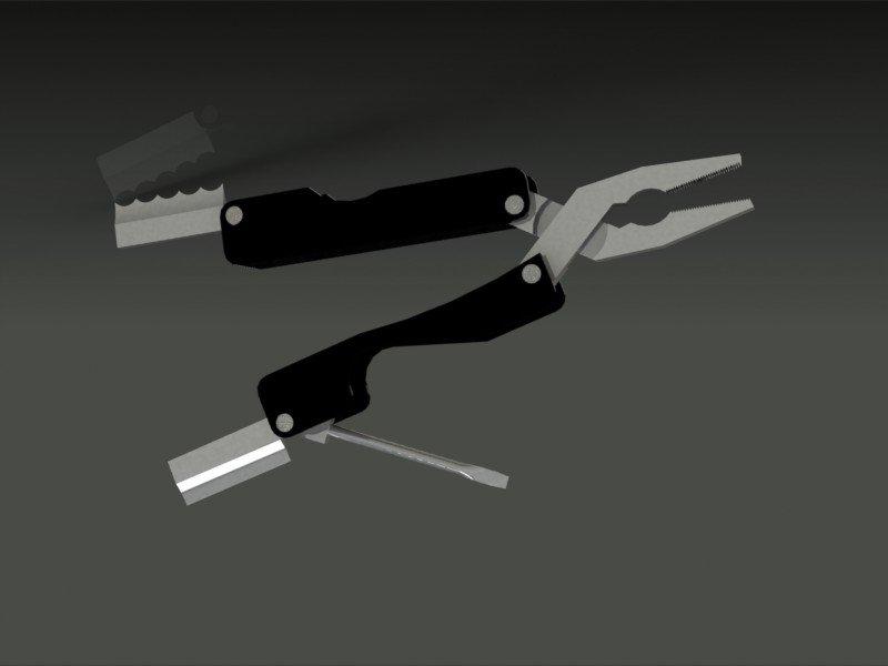
as a class exercise. We will also cover the Mechanical Claw this
week. |
In
Class exercises and assignment details:
-
In Class Evaluation (ICE) (3
items). Click here for your Week
4 ICE Evaluation Check List, print this out, fill in the needed information,
follow the instructions and hand it in at the end of the evaluation at
the instructor's desk. On the first day of class this week we will have
an evaluation of the models completed so far through Week 3. The
evaluation criteria will include:
-
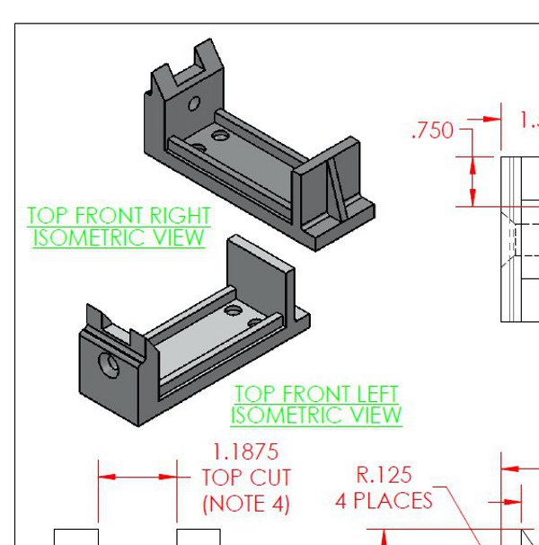
Control Block (20 pts),
Download drawing pdf: Control
Block Drawing. Model this part as shown, fillets are features,
maintain symmetry, looking for a feature mirror.
-
Completeness with symmetry (1pt)
-
Units, material (1pt)
-
Correct starting plane (1pt)
-
Fully defined sketches with
dimensions (3pts)
-
Precision to 4 units after the
decimal for the required dimensions (1pt)
-
Hole Wizard for left Guide Hole,
Top Slot, Side Guide, Side Guide Mirror, Right Rib, Hole Wizard for Mounting
Holes, Feature Fillet (1pt each)
-
Mass, precision to 4 units after
the decimal (3pts) Center of Mass (3pts)
-
Extras and errors
Control Block
partial drawing image
-
Mystery Part and Assembly (10pts)
-
Material (both parts) (1pt)
-
Named features (both parts)
(2pts)
-
Symmetry (1pt)
-
Proper dimensions and relations
to match (2pts)
-
Fully defined sketches with
dimensions in whole values (2pts)
-
Assembly properly mated (2pts)
-
Extras and errors
-
Assembly Model (20 pts), looking
for 3 parts
-
Material (1pt for each part)
(3pts)
-
Symmetry (1pt for each part)
(3pts)
-
18 Sketch Relation groups, Dimensions
and Reference Geometry items on your most complex sketch (1pt for each
part) (3pts)
-
Fully defined sketches with
appropriate dimensions and relations (2pts for each part) (6pts)
-
4 features on each part (1pt
for each part) (3pts)
-
Hole Wizard (1pt)
-
Slot Sketch (1pt)
-
Assembly and extra parts for
extra credit
-
The Tutors, 1 and 2.
We will model as demonstrated in class. If you model these outside
of class rearrange the features of Tutor 1 to resemble the image
nearby. This will make it more realistic and manufacturable.
 Out of Class Design Assignment
details:
Out of Class Design Assignment
details:
-
ED Book
-
Complete the Guide-Rod
assembly, follow the book in Lesson 2
-
Ex 2.2, use the "Hook.SLDPRT"
file from your book CD, create the pin (to have a clearance fit, defined
length of your choice), create the Flatbar from the Instructional
Videos below for the Link.
-
Ex 2.8
-
use the Link created
in the "Configurations, Design Tables and Equations" videos listed below.
-
Make the Base symmetric, front
and back, left and right.
-
Make the link mounts symmetric
as well and forked as shown.
-
incorporate components of the
the "Weight-Hook" assembly from exercise 2.2 above.
-
A minimum of 3 links plus the
Weight
and Hook items.
-
Be creative with your designs.
-
VD The Configurations, Design
Tables and Equations videos below.
-
SW Tutors 1 and 2 follow
the instructions in the SolidWorks tutorials.
-
Complete your Assembly Model
parts, work on the assembly, per the criteria in Week 3.
Instructional Videos:
-
View this
week's Instructional Videos at this links on the listed subjects below:
136.
SolidWorks, Creating our CAD Lab Assembly Template File, Inches, Millimeters
118.
Configurations, Design Tables & Equations, Part 1, An Introduction
119.
Configurations, Design Tables & Equations, Part 2, New Configurations
120.
Configurations, Design Tables & Equations, Part-3, Configuration Feature
Suppression
121.
Configurations, Design Tables & Equations, Part 4, Derived Configurations
122.
Configurations, Design Tables & Equations, Part 5, Creating a Design
Table
123.
Configurations, Design Tables & Equations, Part 6, Design Table, Excel
Automation
The
following 2 videos are optional, if you are interested in equations to
continue to automate your designs:
124.
Configurations, Design Tables & Equations, Part 7, Equations
125.
Configurations, Design Tables & Equations, Part 8, More Equations
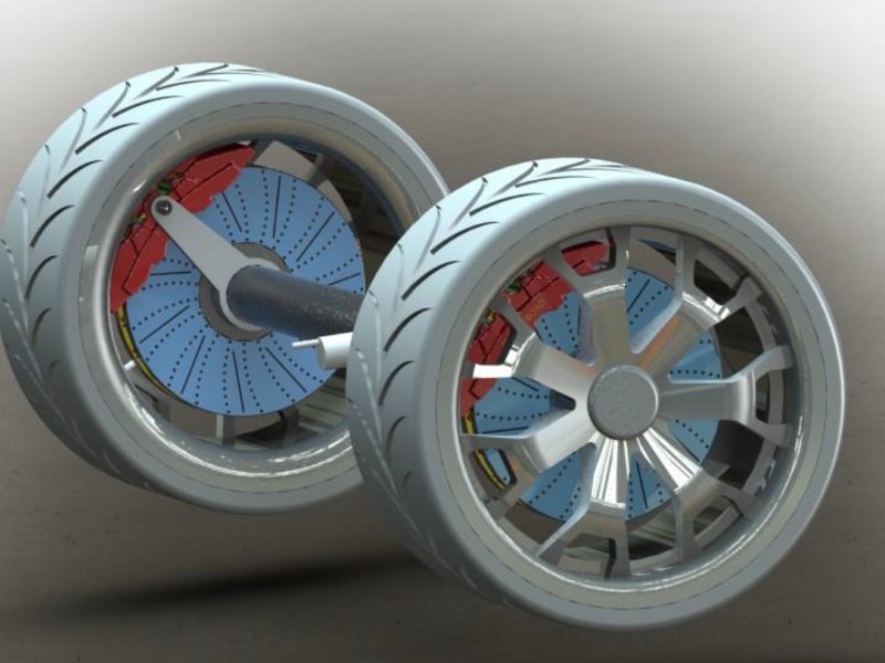
The
following videos are optional, if you are interested in applying a Path
Mate (for some motion control) or creating a wheel and tire assembly for
your projects.
56.
Applying the Path Advanced Mate, Part 1, Adding the Path Sketch
57.
Applying the Path Advanced Mate, Part 2, Adding the Vertex, Applying the
Mate
59.
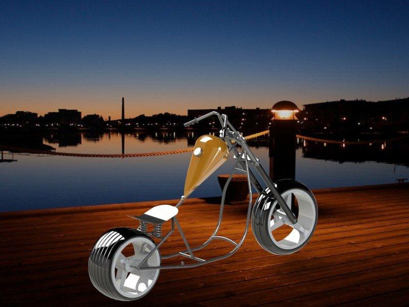
Creating a Simple Wheel-Tire Assembly, Part 1, The Wheel
60.
Creating a Simple Wheel-Tire Assembly, Part 2, The Tire
61.
Creating a Simple Wheel-Tire Assembly, Part 3, Tire Treads
62.
Creating a Simple Wheel-Tire Assembly, Part 4, The Assembly
The
SolidWorks Mass Properties inconsistency class video:
SolidWorks
Mystery, An Inconsistency in the Mass Properties on a Simple Part
The
following 2 videos are optional. A student requested some help on
using some simple representations of spur and bevel gears which are demonstrated
in the videos below:
137.
SolidWorks, Simple Bevel Gear Friction Wheel Demo using the Gear Mate,
Mechanical Mate
138.
SolidWorks, Simple Spur Gear Friction Wheel Demo using the Gear Mate, Mechanical
Mate
|
- |
|
|
 |
|
-
| Week
5:
Design
Assignments due:
The Link
is available below. Additional videos regarding your ICE are also
available in the Instructional Video section below.
On the
first day of class this week come to class with the completed assignments
through Week 4 in preparation for your In Class Evaluation (ICE).
Most of the Control Arm Assembly can be assembled before class.
Make certain you read the section below and get this accomplished before
class. You can use this partial assembly during the ICE. The
ICE will be due as a redo by Friday by 5pm.
New Instructional
Videos have been posted below covering assembly techniques and using the
"Pack and Go" function. Scroll down to the Instructional Video section
below for more information. |
In
Class exercises and assignment details:
-
In Class Evaluation (ICE) (4
items). Click here for your Week
5 ICE Evaluation Check List, print this out, fill in the needed information,
follow the instructions and hand it in at the end of the evaluation at
the instructor's desk. On the first day of class this week we will have
an evaluation of the models completed so far through Week 4. The
evaluation criteria will include:
-
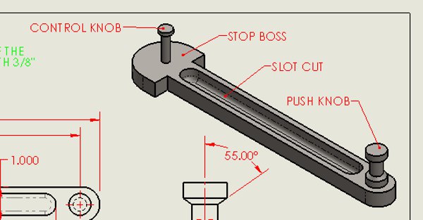
Control
Arm (20pts), Download drawing pdf: Control
Arm Drawing. Model this part as shown,
fillets are features, maintain symmetry, looking for a revolve feature.
-
Completeness
with symmetry (1pt)
-
Units,
material (1pt)
-
Correct
starting plane (1pt)
-
Fully
defined sketches with dimensions (3pts)
-
Precision
to 4 units for appropriate dimensions (1pt)
-
Revolved
Feature for the Push Knob (2pts) Feature Full Round Fillet (2pts)
-
Rename
features (1pt)
-
Mass,
precision to 4 units after the decimal (4pts) Center of Mass (4pts)
-
Extras
and errors
Control Arm partial
drawing image
-
Control
Arm Assembly (20pts), Send all parts and the assembly, use Pack and
Go, this is an assembly for the Mounting Plate, Control Block, Control
Arm and the Links. Download
the Link here.
-
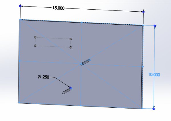
MountingPlate,
15 x 10 x 0.5" (1pt) fixed and to the origin (1pt) at least 2 Mounting
Posts for mounting the Links (1pt), Hole Wizard holes to match the
Control
Block hole locations (just a Hole) in a location of your choosing,
probably best in a corner (1pt)
-
ControlBlock
fully defined on the Mounting Plate (use mounting holes) (1pt),
ControlArm
centered on Control Block (use your planes) (1pt), with exposed
material on both ends (1pt),
-
Modify
your Link to add a slot cut feature on the Lever that is the same
diameter as the existing holes (1pt) center line 1.25 (1pt), concentric
relation on the round end (1pt)
-
Control
Arm, limit mate between the Control Block and the Stop Boss
on the Control Arm (1pt)
-
3 Links-as
made from the videos, with 3 different lengths to provide linear motion
of the Control Arm on the Control Block (1pt), mate the plane
of the Slot Cut on the Link with the axis of the Control Knob (2pts),
coincident mates between the Links and the Mounting Posts (1pt),
concentric mates between the Links and the Mounting Holes on the
Mounting
Plate, locations of your choosing (1pt), motion through 3 Links
and the Control Arm (2pts), Control Arm displacement
of more than an inch (2pts)
-
Extras
and errors
Mounting Plate example
showing the Mounting Posts and holes for the Control Block.
Notice that the Mounting Posts do not have any dimensions on them yet,
keep these undimensioned while you are placing your Links.
-
Mystery
Assignment (20pts), Send all parts and the assembly, use Pack and
Go
-
Moves
as intended (3pts)
-
Base,
fully defined (1pt), symmetry (1pt), symmetry of the Link mounts
(1pt)
-
Links-as
made from the videos (5pts), 4 different lengths (2pts), all coincident
mates with adjacent parts (1pt), all concentric mates with adjacent parts
(1pt), extra Link to maintain symmetry with the Link mounted
on either side of a symmetric Link or part (1pt)
-
Sub-assembly
as demonstrated in class (1pt), flexible to the master assembly (1pt)
-
Extra
credit for a parallel type mate (2pts)
-
Extras
and errors
-
Assembly
Model on Monday, a more complete evaluation will be on the model submitted
by Friday (20 pts), looking for 3 parts below
-
Material
(1pt for each part) (3pts)
-
Symmetry
(1pt for each part) (3pts)
-
18 Sketch
Relation groups, Dimensions and Reference Geometry items on your most complex
sketch (1pt for each part) (3pts)
-
Fully
defined sketches with appropriate dimensions and relations (2pts for each
part) (6pts)
-
4 features
on each part (1pt for each part) (3pts)
-
Hole Wizard
(1pt)
-
Slot Sketch
(1pt)
-
Assembly
and extra parts for extra credit.
Out of
Class Design Assignment details:
-
ED Book:
-
Download the models from the
book CD for exercises 2.5 and 2.6. Use these models to practice the
various Advanced and Mechanical assembly mates.
-
SG Book.
-
Lesson 5, Bearing Blockassembly
assignment with Toolbox items, download zip file here: Bearing
Block Parts.
-
Download the parts and assemble
this model per the image nearby
-
Rework each part, using the
Roll Back Bar, to make each part symmetrical using techniques exercised
in class.
-
"Bearing Block" fixed to the
origin and on top of the Feature Manager Tree
-
Modify the "Bearing Block" part
so that the Hole Wizard Holes match the options in the Bearing Plate
-
Mate each part using the primary
planes, Hole Wizard holes and surfaces
-
Apply the fasteners per the
SG book taking in consideration the sandwiched "Bearing Plate".
-
Mate the fasteners so that they
do not rotate using techniques from the ED book.
-
Lengthen the "Pan Cross Head"
bolts to be just about at the end of the "Hex Nut".

Instructional Videos:
Putting
the Slot Cut in your Link
How
Sketch Elements are Counted for your Evaluations
How
to Start your Linkage Assembly
142.
SolidWorks, Using the "Pack and Go..." Function
144.
Basic Assembly Techniques, Part 1, Getting Started, Part Configurations,
Temporary Axes
145.
Basic Assembly Techniques, Part 2, Smart Mate
146.
Basic Assembly Techniques, Part 3, Using the Toolbox, Screws, Washers,
Nuts, Smart Mates
147.
Basic Assembly Techniques, Part 4, Exploded View Configuration, Explode
Line Sketch
148.
Basic Assembly Techniques, Part 5, Animate Collapse, Rename and Reorder
Steps
The
following 4 videos are optional, if you are interested, and were requested
by some students:
139.
SolidWorks, Modeling a Spring for an Interactive Assembly, Part 1, Helix
and Various Options
140.
SolidWorks, Modeling a Spring for an Interactive Assembly, Part 2, Fix
the Spiral, non Helix Sweep
141.
SolidWorks, Modeling a Spring for an Interactive Assembly, Part 3, Details,
In Context Assembly
143.
Chain Segment Motion with Sprockets in an Assembly with the Path Mate (also
see 175 and 176)
|
- |
|
|
 |
|
-
| Week
6:
Your
first exam is on Monday of this week. Information on the modeling
portion of the exam can be found in this section below. More information
will be added before Sunday.
Start
Project 3, on engineering drawings, in the ED book and start putting together
drawings for your Assembly Model parts and assembly. |
In
Class exercises and assignment details:
-
You will
have your first examination on Monday of this week in 2 parts. The
written portion will be per the syllabus and the design assignment portion
will be as described below:
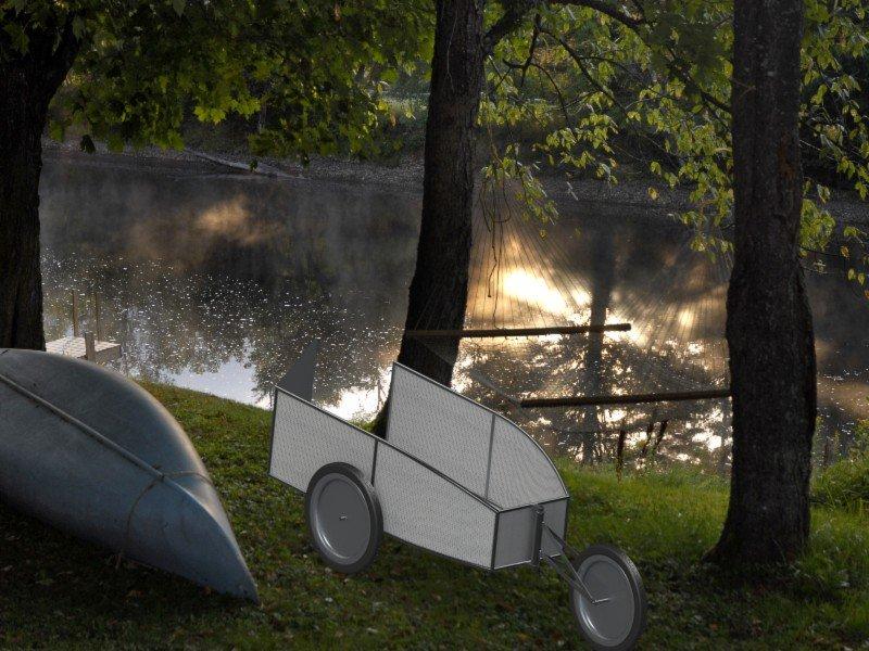
-
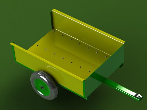
The Garden
Cart
-
Model
the cart as described below. Before class on Monday you will: download
some parts, create some parts, and create a partial assembly. On
Monday you will create a part in class in a similar manner as our evaluations,
modify some existing parts then finish your partial assembly with parts
and toolbox items. The requirements may change, please check back.


-
Parts
to download (more coming soon)
-
go to
3D
Content Central and download a cotter pin, scale this up or down as
needed. Also look up garden hose.
-
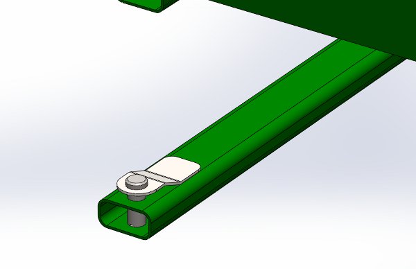
Cart
Hitch Top, fully
define this considering the hitch hole on the Cart Floor Support. Full
round Fillet on the front, 1/2" fillet on the back per the image below.
Insert a Clevis Pin from the Tool Box, fully define this.
-
Parts
to Model out of class:
-
The Cart
Floor Support, Plain Carbon Steel, use the profile in the image below,
start with a center rectangle, sketch fillets and an offset, on the appropriate
plane (think about the cart orientation), look up the standard sheet steel
gauge for wall thickness, extrude to 44 inches, Hole Wizard holes (sized
in class) Clearance holes, Create a Configuration named "Center" that adds
20 inches on the front of the support, place a 7/8" hole for a hitch in
the front, set back 1" symmetric. Hole Wizard holes are also on the
Center Configuration.

-
Axle,
Plain Carbon Steel, Fixed to the origin in the assembly, 0.75" diameter,
41 inches long, cotter pin hole on the top plane at 1.0" from each side
and 3/16" in diameter, 1/16" chamfer at 35 degrees on each end, Cosmetic
Thread 3/4-10, 3/4 inch long, both ends, show this.
-
Wheel
Tire subassembly, mate both elements fixed to the origin
-
Wheel,
AISI 304, revolved feature per the image below.
-
Tire,
Rubber, revolved feature using the parameters from the wheel, extra credit
for extra details.
-
Parts
to Model in class: The Wheel Mount with a Right, Left and Center configuration.
-
Assembly
tips:
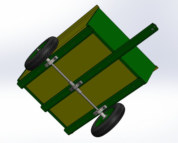
-
There
should be no material interferences like with the Panels on the
Cart
Floor Supports.
-
Panelsshould
be flush with the ends of the Cart Floor Supports.
-
Remember
to consider your SolidWorks planes for mating, all of your parts, if built
with symmetry in mind, should have these available, mate these part planes
with the associated plane of the assembly.
-
Out
of Class Design Assignment details:
-
ED Book
-
Project 3 to create your ANSI
B drawing template file, see details in the Drawing
Template File section below. Also see the videos in the Instructional
Video section below.
-
Assembly Model part (of your
choice) drawing using the Guide drawing in Project 3 as an example
to follow, see details in the Assembly
Model parts and assembly drawings section below.
-
Assembly Model Exploded View
drawing with a BOM and balloons using the Guide-Rod assembly
drawing in Project 3 as an example to follow, see details in the Assembly
Model parts and assembly drawings section below.
-
Final Project Abstract
-
Click here for a grading guide
on your Final
Project Abstract
-
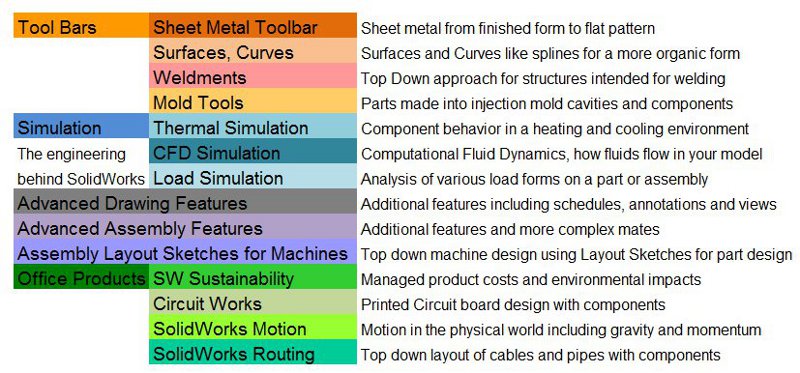
Choose a toolbar or function
to study practice and then demonstrate during your Final Project
presentation from the categories or subcategories listed below, if you
want to choose something different from what is listed please see me.
-
Specific Information on your
Drawing
Template Files - Back to
Out of Class Design Assignment Section
Follow the book with the
following exclusions, inclusions and modifications as listed below.
-
Create the Millimeter file first,
save it, then resave it as your inches file making the appropriate changes
for the units. Start from the beginning of the project and follow
all of the steps listed.
-
Page 3-9, the bottom of the
page, when it discusses the units make certain that you also assign inches
as the "Dual Dimension Length" with 3 units after the decimal (like we
have been doing all quarter)
-
Save your file to "DRAW-MM-ANSI"
in your template folder.
-
Page 3-10, top of the page,
make certain your font and text size are as described (the default annotation
size is set at about 1/8" which is appropriate for large text, notes and
smaller text will be about 3/32", we will use this when needed in class)
-
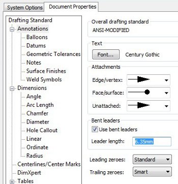
Page 3-10, middle of the page,
change the bent leader to a length of 2mm as opposed to the default value.
You will find this location using information in the image below.
-
Page 3-11, top of the page,
Create the following layers and setting as listed below:
-
name: Titeblock-Border, color:
Dark Blue
-
name: Dimensions, color: Red
-
name: Sheet Notes, color: Green
-
name: Hidden Dims, color: Blue
(turn off this layer)
-
Page 3-13, middle of the page,
know about "Edit Sheet" and "Edit Sheet Format" for the test.
-
Page 3-14, bottom of the page,
enter your company name not D&M and the font size and style of your
choosing, make certain it fits the space it is located in on the Title
Block.
-
Page 3-15, bottom of the page,
insert the drafting standard notation ANSI Y14.5 in addition to and after
the text that is provided
-
Page 3-16, top of the page,
make certain that you change the millimeter values to inch equivalents
when you make your inch template file, you will be graded on this!
-
Page 3-17, top of the page,
create a logo using the following guidelines in a style of your choosing.
-
Include a company name, address,
phone number and website address below, nearby or included in your logo.
-
Choose a name and style that
fits your career ambitions or personality. You may design something
in SolidWorks, AutoCAD, Paint, Photoshop, Word or another design program.
Use the following criteria:
-
Your logo must be unique, no
credit for someone else's work
-
An image
-
Inserted to the left or in between
the Proprietary and Confidential box in the titleblock
-
Draw sketch lines around it
(on the Titeblock-Border layer) and make the logo fit the space and look
neat
-
Does not have to look 3D or
in color (they usually are not in color on engineering drawings)
-
Include some graphical styling
including various line sizes, fonts, hatching and other techniques
-
extra credit for extra design
styling
-
Below is my logo and would represent
a design that meets the criteria described above.
-
Below are some additional logos
from various engineering and architectural drawings that I have found over
the years. These were designed in AutoCAD.

-
Save your file then resave it
as your inch template, change all of the annotations and settings to inches
then save your file.
-
-
Drawing assignments - Back
to Out of Class Design Assignment Section
Once you have completed
your drawing template files you can use them for your
Assembly Model
parts and assembly drawings Design Assignments due this week.
Insert the "Guide" and "Guide
Rod Assembly" for an Exploded View, as described in the rest of Project
3. Concurrent with the "Guide" and "Guide Rod Assembly" insert your
more detailed part from your Assembly Model and your Assembly
Model assembly design from last week into two similar drawings using
the same parameters as described in the book.
Instructional Videos
75.
Creating a Part Drawing, Part 1, Layout the Views
76.
Creating a Part Drawing, Part 2, Editing the Title Block
77.
Creating a Part Drawing, Part 3, Auxiliary View, Various View Options
78.
Creating a Part Drawing, Part 4, Section and Detail Views, View Titles
79.
Creating a Part Drawing, Part 5, Managing Annotations
80.
Creating a Part Drawing, Part 6, Inserting and Managing Dimensions
81.
Creating a Part Drawing, Part 7, Drawing Cleanup
82.
Creating a Part Drawing, Part 8, More on Drawing Cleanup
50.
Explode Assembly Drawing, Part 1, Explode Line Sketch
51.
Explode Assembly Drawing, Part 2, Inserting Assembly into Drawing
52.
Explode Assembly Drawing, Part 3, Inserting the BOM, Bill of Materials
53.
Explode Assembly Drawing, Part 4, Modifying the BOM, Bill of Materials
54.
Explode Assembly Drawing, Part 5, More on Modifying the BOM, Bill of Materials
55.
Explode Assembly Drawing, Part 6, Adding and Modifying the Balloons
|
- |
|
|
 |
|
-
| Week
7:
Design
Assignments due: On the first day of
class this week come to class with the completed assignments through Week
6 in preparation for your In Class Evaluation (ICE). details below.
Video
links will be added soon. |
In
Class exercises and assignment details:
-
In Class Evaluation (ICE) (4
items). Click here for your Week
7 ICE Evaluation Check List, print this out, fill in the needed information,
follow the instructions and hand it in at the end of the evaluation at
the instructor's desk. On the first day of class this week we will have
an evaluation of the models completed so far through Week 6. The
evaluation criteria will include:
-
Final Project Abstract (20pts
toward your Final Project grade.
-
Assembly Model Part Drawing
(15pts)
-
Front, Top, Right, Views (3pts)
-
Section View (1pt) Auxiliary
View (1pt), Detail View (1pt)
-
Appropriate annotations for
the sections, details and auxiliary views (1pt)
-
Views laid out with equal spacing
between left right and top and bottom (1pt)
-
Appropriate dimensions (3pts)
neat and orderly (2pts) Dimension layer (1pt)
-
View labels for each view (1pt)
on Sheet Notes layer (1pt)
-
Errors and Extras
-
Assembly Model Assembly Drawing
(15pts)
-
All Parts (3pts)
-
Exploded view, shaded with edges
(2pts)
-
Explode line sketches (1pt)
-
Explode neat, orderly, easy
to read (1pt)
-
Bill of materials with Item
Number, Description, Material, Part Number and Qty columns filled in (3pts)
-
BOM neat and orderly (1pt)
-
Balloons (1pt) with circular
split line for Item Number and Qty (2pts)
-
Balloons neat and orderly (1pt)
-
Errors and Extras
-
Title Block Items (10pts)
-
All items apparent (1pt)
-
Company name filled in and in
border (1pt)
-
File name fits (1pt)
-
Unless Otherwise Specified section
filled in properly (1pt)
-
Interpret Geometric Tolerancing
section filled in properly (1pt)
-
Logo, effort, unique, (2pts)
fills the box, company name, address, phone number, web address (2pts)
-
Proprietary section filled in
(1pt)
-
Bearing Plate Block Assembly
(20pts)
-
Complete with all of the parts
(3pts)
-
Take the unsymmetrical parts
and make them symmetrical (3pts)
-
Rename the Bearing Block part
to Bearing Block New (1pt)
-
Bearing Block New part fixed
to the origin and on top of the Feature Manager Tree (2pts)
-
Modify the Bearing Block New
part so that the Hole Wizard Holes match the options in the Bearing Plate
(2pts)
-
Install or redefine the mates
for the Bearing Plate assembly fasteners to the back of the Bearing Block
New part in the new assembly (2pts)
-
Lengthen the Pan Cross Head
bolts to be just about at the end of the back of the Hex Nut. (2pts)
-
Components properly mated with
the Bearing Plate in the middle and everything fully defined including
fasteners (5pts)
-
Extras and errors
Out of
Class Design Assignment details:
-
ED Book, exercises 4.3, 4.5
and 4.7. An ICE model next week resemble one of these designs.
-
VD (optional for Extra Credit)
creation of a door model, refer to the Instructional Video links below
-
Use the rendering program PhotoView
360, by way of the video links below, to render the image of your model
for the Week 8 image contest, see details below.
-
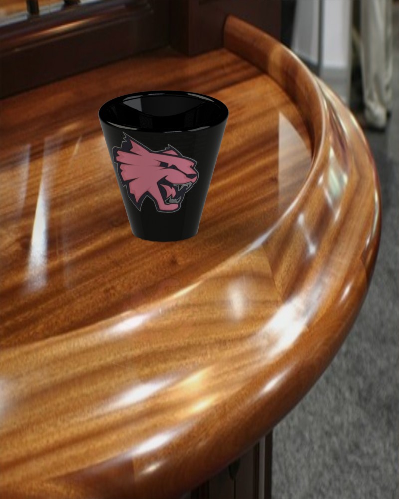
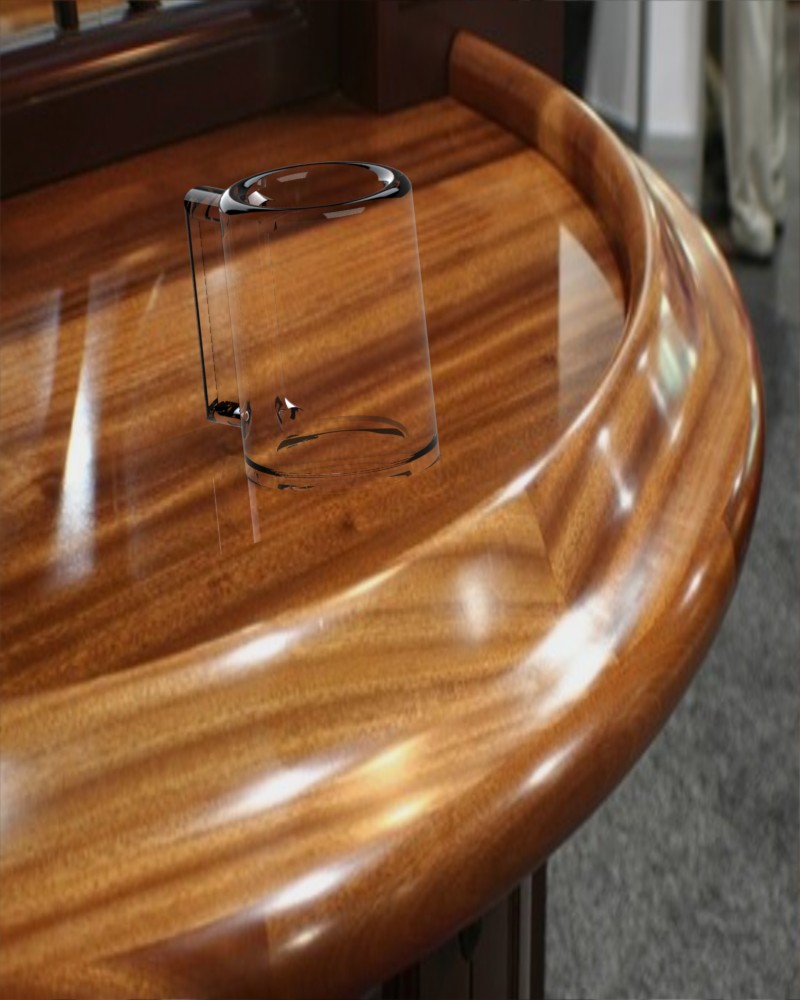
SG Book, design 3 revolved feature
parts:
-
Lesson 9, design 3 revolve features
parts and a photo real image per the requirements below. Photo real
image(s) (you can submit more than one) are due by Sunday by 5pm of Week
8 via email. The part models are due on Monday for the ICE, both
the image and the models are required:
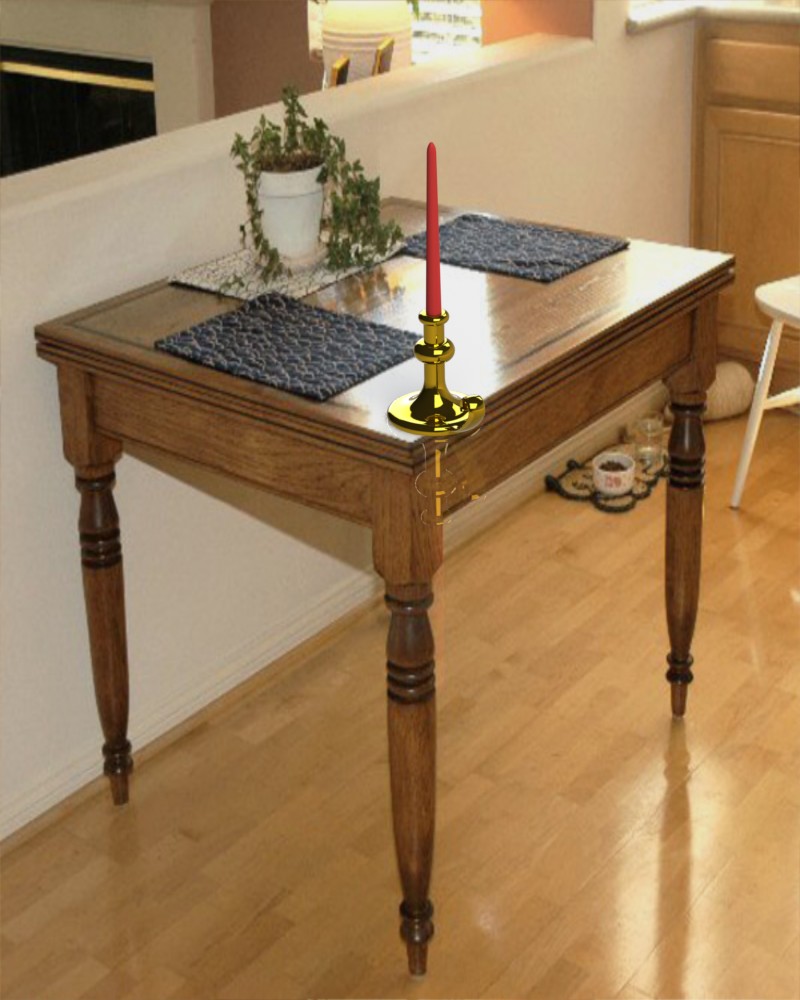
-
The first part needs to resemble
a vase or candlestick similar to the image on page 111
-
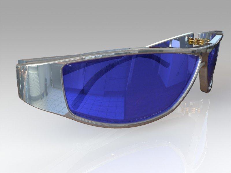
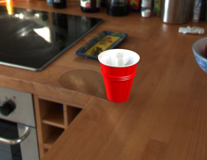
The other parts use a revolved
feature of your choice (bowls, drinking glasses, wine glasses, cups, trays,
tops, lamps, lighting fixtures, hub caps, lids, fasteners, etc... anything
that can be created using a revolved feature)
-
All part sketches are fully
defined, unless using splines. However if you want to fully define
your splines at the end of your design use the "Fully Define Sketch" option
then round the resulting dimensions up or down to a lower precision.
-
Use the rendering program PhotoView
360, by way of the video links below, to render the image of your model
for the Week 8 image contest, see details below.
-
Image Contest details:
-
Choose your best revolved part(s)
to create a photo real image, Using PhotoView 360 (see videos below), per
the following requirements. The class will vote on the best images
during the Week 8 ICE:
-
Model needs to fill the image
-
Using the PhotoView 360 Options
choose the following options:
-
choose "Best" resolution
-
jpg format
-
800 pixels wide, variable height
as needed
-
In the Display Manager tabs
select
-
Appearances, choose an appearance
if you don't have or don't like the material selected on the part
-
Decals only if appropriate,
if chosen do not use the default ones create your own for extra credit
-
Scenes, choose a scene
-
Lights, add custom Spot or Point
light with settings other than default, make certain you turn these on
for PhotoView 360
-
Define a camera position and
use this for your image
-
Prizes:
-
1st place champion 30pts extra
credit
-
2nd place winner 20pts extra
credit
-
3rd place winner 10pts extra
credit
Instructional Videos
67.
Using Splines in Revolved Features, Part 1, Sketching and Modifying a Spline
68.
Using Splines in Revolved Features, Part 2, More on Modifying a Spline
69.
Using Splines in Revolved Features, Part 3, More on Modifying a Spline
and Curvature
70.
Using Splines in Revolved Features, Part 4, Offsetting the Spline and Finishing
the Model
34.
PhotoView 360, Part 1, Materials and Appearances to the Door and Bodies
35.
PhotoView 360, Part 2, Rendering Primer and Decals
36.
PhotoView 360, Part 3, Using Scenes
37.
PhotoView 360, Part 4, More on Scenes and Adding and Managing Lights
38.
PhotoView 360, Part 5, More on Scenes and Managing Lights
39.
PhotoView 360, Part 6, More on Scenes and Managing Camera Views
40.
PhotoView 360, Part 7, Options for Rendering and Saving
The
following videos are voluntary and the resulting door model can be created
for extra credit.
17.
The "Door", Part 1, Basic Door Related Measurements
18.
The "Door", Part 2, More Door Measurements
19.
The "Door", Part 3, Sketching the Door Panel Geometry
20.
The "Door", Part 4, More on Panel Sketching with Fillets and Chamfers
21.
The "Door", Part 5, Finishing the Panel Sketching and Features
22.
The "Door", Part 6, Panel Mirroring Options for Sketches and Features
23.
The "Door", Part 7, Sketching for a Window Cut
24.
The "Door", Part 8, Inserting a Window, as a Separate Body in our Door
Part
25.
The "Door", Part 9, Window Glass Appearance and Scenes
26.
The "Door", Part 10, Creating a Door Knob, as a Separate Body in our Door
Part
27.
The "Door", Part 11, Using the Mirror Feature and Appearance Mapping
|
- |
|
|
 |
|
-
| Week
8:
Design
Assignments due: On the first day of
class this week come to class with the completed assignments through Week
7 in preparation for your In Class Evaluation (ICE). details below.
|
In
Class exercises and assignment details:
-
In Class Evaluation (ICE) (6
items). Click here for your Week
8 ICE Evaluation Check List, print this out, fill in the needed information,
follow the instructions and hand it in at the end of the evaluation at
the instructor's desk. On the first day of class this week we will have
an evaluation of the models completed so far through Week 8. The
evaluation criteria will include:
-
The Revolved Part1 (10 pts)
-
Completeness with symmetry
(2pts) Material (1pt)
-
Fully defined sketches (1pt)
whole unit dimensions (2pts) sketch relations (2pts)
-
Extra sketches and features
(0.5pt each) Errors
-
The Revolved Part2 (10 pts)
-
Completeness with symmetry
(2pts) Material (1pt)
-
Fully defined sketches (1pt)
whole unit dimensions (2pts) sketch relations (2pts)
-
Extra sketches and features
(0.5pt each) Errors
-
The Revolved Part3 (10 pts)
-
Completeness with symmetry
(2pts) Material (1pt)
-
Fully defined sketches (1pt)
whole unit dimensions (2pts) sketch relations (2pts)
-
Extra sketches and features
(0.5pt each) Errors
-
The Revolved Part Image (10
pts)
-
Model needs to fill the image
(2pts)
-
Choose "Best" resolution (2pts)
-
jpg format (1pt)
-
800 pixels wide, variable height
as needed (2pts)
-
Decals, create your own for
extra credit (EC 1pt)
-
Scenes, choose a scene, not
the default (1pt)
-
Lights, add custom Spot or Point
light with settings other than default, make certain you turn these on
for PhotoView 360 (1pt)
-
Define a camera position and
use this for your image (1pt)
-
Extra credit for extra effort
and extra images
-
Vote on the Revolved Features
part image from Week 8 in the Design Gallery on the website that you find
exceptional. Vote for your first 3 choices by number. (10pts).
1st choice __________
2nd choice __________ 3rd choice __________
-
Mystery Part (20pts),
Modeled from the ED book
-
Completeness with symmetry (1pt)
-
Units, material (1pt)
-
Correct starting plane (1pt)
-
Fully defined sketches with
dimensions (2pts)
-
Dual dimensions, inches on top,
mm on bottom in brackets (2pts)
-
Features: Base (1pt), others
(3pts)
-
Rename features (1pt)
-
Mass, precision to 3 units after
the decimal (4pts) Center of Mass (4pts)
-
Extras and errors
-
Panametric Fam (20pts),
See image below, model this part as shown in the drawing, download part
drawing: Panametric
Fam
-
Completeness with symmetry (1pt)
-
Units, material (1pt)
-
Correct starting plane (1pt)
-
Fully defined sketches with
dimensions (2pts)
-
Features in order: Base (1pt),
Fillets (1pt), Side Cut (1pt), Ears and Holes (1pt), Ear Holes Mirror (1pt),
Hole Wizard (1pt)
-
Rename features to above (1pt)
-
Mass, precision to 3 units after
the decimal (4pts) Center of Mass (4pts)
-
Extras and errors

Out
of Class Design Assignment details:
-
ED Book, Project 4 (from Week
7) and Project 5, skip the section on Mold Tools in Project 4. Ex
5.7, Flange Pipe, information on this soon and will involve revolve, sweep
and lofted (using guide curves) features.
-
SG Book, Lesson 10, model the
Chisel and Screwdriver.
-
Threaded Fastener Assignment
-
Spur Gear Design Assignment
Instructional Videos
84.
Spur Gear Design Assignment, Part 1, Assembly and Theory
85.
Spur Gear Design Assignment, Part 2, Starting the Tooth Profile Sketch
86.
Spur Gear Design Assignment, Part 3, More on the Tooth Profile Sketch
87.
Spur Gear Design Assignment, Part 4, Extruding the Tooth Profile and Circular
Pattern
88.
Spur Gear Design Assignment, Part 5, The Spur Gear Assembly
149.
Creating a Lofted Boss/Base on a Simple Part, Options, Guide Curves
|
- |
|
|
 |
|
-
| Week
9:
Design
Assignments due:
On the
first day of class this week come to class with the completed assignments
through Week 8 in preparation for your In Class Evaluation (ICE).
details below.
GD&T
will be the focus for this week's lecture topics. |
In
Class exercises and assignment details:
-
In Class Evaluation (ICE) (6
items). Click here for your Week
9 ICE Evaluation Check List, print this out, fill in the needed information,
follow the instructions and hand it in at the end of the evaluation at
the instructor's desk. On the first day of class this week we will have
an evaluation of the models completed so far through Week 9. The
evaluation criteria will include:
-
Threaded Fastener (20pts)
-
Correct starting plane (1pt)
ring shank feature correct direction (1pt)
-
Bolt Diameter (1pt), Length
(1pt), Thread length (2pts)
-
Head Chamfer Revolve (2pts)
-
All features correct as shown
(5pts)
-
Sweep Profile (5pts) Helix pitch
(2pts)
-
Extras and Errors
-
Spur Gear (30pts)
Pinion Wheel
-
Do, Dp, Dr, (3pts each)
-
Dpp, Db (4pts each)
-
Ta (2pts each)
-
Tooth Root Perpendicular (2pts
each)
-
Xc (1pt)
-
Significant digits (1pt)
-
Movement with Physical Dynamics
(6pts)
-
Extras and Errors
-
Mystery Part, SG
(10pts)
-
Completeness with symmetry (1pt),
relocate the origin on the handle (1pt)
-
Fully defined sketches with
proper dimensions and sketch relations (2pts)
-
Color (1pt)
-
Rename your features (1pt)
-
Proper Loft Feature (2pts)
-
Loft Start/End Constraints:
start - Tangency to Face, end - Normal to Profile (2pts)
-
Extras and errors
-
Mystery Part, ED Book
(10pts), from Project 5 (one ED project part for points and the other extra
credit, done before class)
-
Completeness with symmetry (1pt)
-
Units, description (1pt)
-
Correct starting plane (1pt)
-
Fully defined sketches with
dimensions (2pts)
-
Features in order: Base (1pt),
Front Cut (1pt), Shell (1pt), Revolve Cut (1pt), Threads (1pt)
-
Extras and errors
-
Mystery Part, ED Book
(10pts), from Project 4 (one ED project part for points and the other extra
credit, done before class)
-
Completeness with symmetry (1pt)
-
Units, description (1pt)
-
Correct starting plane (1pt)
-
Fully defined sketches with
dimensions (2pts)
-
Features in order: Base (1pt),
Side Fillets (1pt), Top Cut and Fillets (1pt), Spring (1pt), Spring Pattern
(1pt)
Extras and errors
-
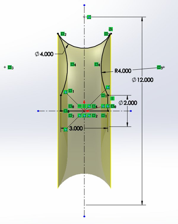
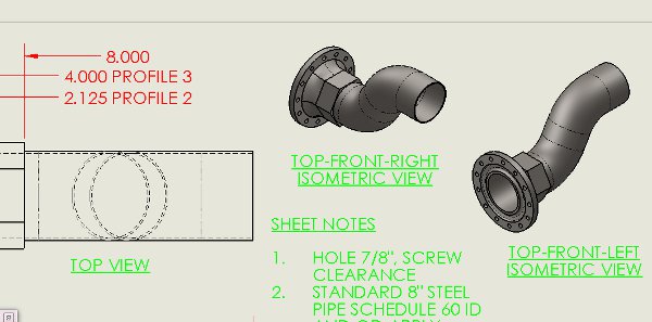
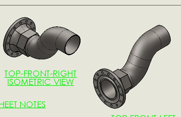
Steel Pipe, an enhancement to
ED 5.7 (30pts) See image below, model this part as shown in the drawing,
download part drawing: Steel
Pipe
-
Completeness with symmetry,
location of the Origin, correct starting plane (2pts)
-
Material, AISI 1015 Steel, Cold
Drawn (SS) (2pts)
-
Use the value for both the outside
and inside diameter of a standard 8 inch, schedule 60, steel pipe from
a table provided by the All Steel Pipe Construction Directory (4pts)
-
Features in order: Flange Base
(1pt), Loft with top and bottom Guide Curves, (1pt), Hexagonal support
base (1pt), Swept solid without the hole (1pt), Gasket Revolved Cut (1pt),
Hole Wizard (1pt), Circular Pattern of the holes (1pt), Swept Cut for the
inside diameter cut of the pipe (refer to All Steel Pipe) (1pt)
-
Rename features to above (2pts)
-
Appropriate precision for various
appropriate dimensions (2pts).
-
Mass, precision to 3 units after
the decimal (4pts) Center of Mass (6pts)
Out of
Class Design Assignment details:
-
GD&T drawings
Create a drawing of your
Steel Pipe ICE model and of one of your parts from your Final Project using
Geometric Dimensioning and Tolerancing items as demonstrated in class this
week. Click
here for your ECL to be included with your drawings and due by Friday
at 5pm in Box.
Instructional Videos
89.
Geometric Dimensioning and Tolerancing, Part 1, Introduction and Symbols
90.
Geometric Dimensioning and Tolerancing, Part 2, Dimensioning Strategies
91.
Geometric Dimensioning and Tolerancing, Part 3, Interference and Clearance
92.
Geometric Dimensioning and Tolerancing, Part 4, 2D and 3D Tolerancing
93.
Geometric Dimensioning and Tolerancing, Part 5, Datums and Feature Control
Frames
94.
Geometric Dimensioning and Tolerancing, Part 6, More on Feature Control
Frames and Online
|
- |
|
|
 |
|
-
| Week
10:
Design
Assignments due:
CSWA
exam on Wednesday, study the appendix section in the ED book to prepare. |
In
Class exercises and assignment details:
-
Exam 2, the CSWA exam.
The following 5 items need to be covered for you to take and get credit
for this exam:
-
Click on the following link
to download your: Tangix
VirtualTester Program. The button is on the upper right side
of the webpage. Download and install this program on your classroom
computer on the day of your exam, Wednesday.
-
Click on the following link
to get a list of your VirtualTester
Voucher Codes (link active soon) referencing your name.
-
Click on the following link
to create a VirtualTester
account, using your email address, so you can receive and publish your
certificate (a requirement for taking and getting credit for this exam),
it will be the third button on the upper left side of the webpage.
Be careful what you enter here; use Captial lettering and proper puncuation
(this is how you will present yourself to the world).
-
Click on the following link
for a video demonstration on how to get published (a requirement for getting
credit for this exam):
Send me your certificate in
pdf format so I can post it on the website (a requirement for getting credit
for this exam).
Out of
Class Design Assignment details:
-
Work on your Final Project.
Instructional Videos
|
- |
|
|
 |
|
-
| Final
Project and presentations, Wednesday, June 5, 4pm to 6pm in the
CAD Lab.
Visit
the links in this section for information on your Final Project. |
Click
on the following links referencing you Final Project:
Presentation
Guidelines: Click on the following link for a document
providing a suggested guideline for your Final Project Presentation. Final
Project Presentation Guidelines. Your SolidWorks model and
presentation materials need to be completed by 3pm in the lab so that they
can be loaded on the instructor's computer before 4pm. Those not
done by this deadline will have points taken off.
Presentation Feedback Forms:
Download
sample form page at this link: Presentation
Feedback Form.
Evaluation
check list: Use this as a guide for preparing for
your Final Project and presentation: Final
Project Grading Criteria. Drawings need to be printed by
4pm. Those not done by this deadline will have points taken off.
Sample
Drawing Images: View the images below and use them
as a guide to layout your own sheet set.

|


 -
-