|
- |
|
|
 |
 |
-
| Week
1:
Before
next Tuesday's class, read the Introduction to your textbook, Introducing
Autodesk Revit Architecture 2011.
| What
is due: On Thursday come to class with a sketched floor plan of a
dream house that you would like to design. You will be modeling this
project throughout the quarter and will ultimately be presenting this design
during finals week as your Final Project. |
On Thursday
we will be covering the basics of this program and will design a simple
house. |
Your sketched floor plan
will be graded on the following criteria:
Your work has to be original
and unique!!
Basic sketch(es) of your
first and second floors.
-
ANSI A size sheet(s)
-
You may want to sketch on two
sheets, one for each floor, if it is too crowded for one sheet.
-
No scaling
-
No wall thicknesses
-
use a single line to denote
interior and exterior walls.
-
Label all rooms
-
At least 8 rooms per floor (not
including closets) or 16 rooms on a single floor
-
stairwells and long hallways
are considered rooms for this evaluation
-
Include a garage (not considered
a room)
-
Include all rooms that would
be appropriate for a house of this size including a utility room, laundry
room and office
Include your name on this sketch(es)
and hand in to the box at the front of the room by Friday at 5pm.
|
- |
|
|
 |
|
-
Week
2:
| Design
Assignment due: Defining a wall structure, page 73. Create
a stacked wall, page 82. |
Start
reading and practicing, with your building model, Chapter 3. |
For Tuesday please begin
to read and practice Chapter 3. Briefly read Chapter 2 but expect
to come back to it in a couple of weeks.
Design Assignment information:
Follow the steps below regarding
defining a wall structure on page 73, then create one of your own.
-
Your wall will have at least
6 elements in it
-
extra credit if you include
more
-
only if it adds to the design
Follow the steps below regarding
the creation of a stacked wall beginning on page 82, then create one of
your own.
-
Your wall will have at least
6 elements in it
-
extra credit if you include
more
-
only if it adds to the design
Both of these assignments will
be graded over the weekend, sent via email.
|
- |
|
|
 |
|
-
Week
3:
| What
is due: Model of your "Dream House" incorporating elements of Chapter 3
as listed below. |
Email
your "Dream House" model via email and hand sketched floor plan via the
Box
by Friday at 5pm. I will take these on the road with me to the conference
and will grade and post the grades the following week. |
"Dream House" model assignment
details:
Create your house complete
with walls, floors, ceilings, doors, windows and roof(s). You do
not have to add any additional components (like plumbing fixtures and furniture).
Include at least the additional details listed below:
-
Levels:
-
1st Floor
-
1st Floor Ceiling
-
2nd Floor
-
2nd Floor Ceiling
-
Roof
-
Walls:
-
At least one each of a basic,
stacked and curtain wall.
-
Show examples of the four different
wall joins
-
Show a non rectangular wall
opening
-
Windows and Doors
-
Show at least 3 examples of
different doors and 4 examples of different windows
-
Floors
-
Design a tapered floor in the
garage
-
Ceiling
-
Insert ceilings of your choice
-
Stairs
-
Insert a stair(s) of your choice
-
Provide a cutout of the stair
penetration on the second floor
-
Roof
-
Insert a roof design of your
choice
-
insert an extruded roof on another
part of your design such as a door entrance.
Make certain that all details
added make sense and fit the model and are correct and complete.
For example, don't just drop a stair into your model at a random location.
These elements need to fit the model, at specific dimensions, and needs
to add to the design.
Extra credit for additional
details beyond the ones mentioned above.
Include your sketched floor
plan by placing it in the box or I will not grade your assignment
for this week.
These details will be similar
to what you will be expected to know for your first mid term examination
on Thursday, February 3rd.
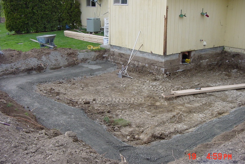
Information on some basic
residential building design elements are shown in the images below.
The images for this week show various elements that go into a simple foundation
and first floor wall construction.
The image below shows the
site work prior to the setting up of the forms for a concrete foundation
footing and stem wall attached to an existing house providing a bedroom
addition.
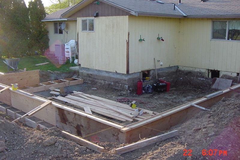
The forms as they are being
set up for the concrete.
The completed forms on the
front of the house as the concrete was being poured.

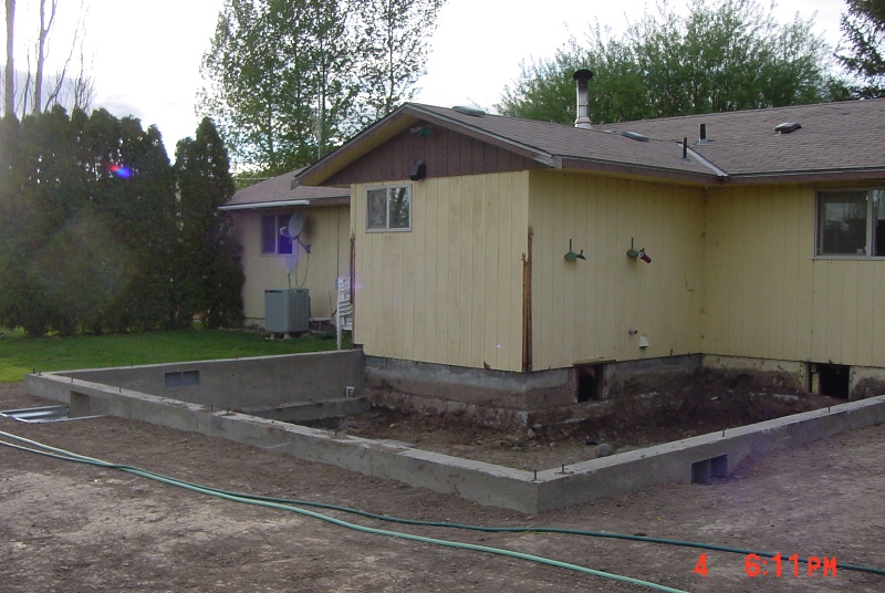
The new footing and stem
wall foundation.
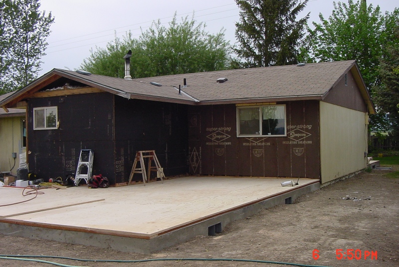
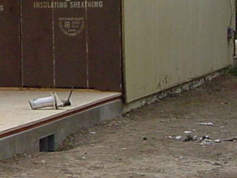
Two days later, the new sub-floor
is constructed on top of the new stem wall foundation. It is this
surface elevation, the top of this floor, that the floor plan with the
interior and exterior walls is designed from. Notice that the exterior
edge of the sub-floor is in line with the edge of the stem wall foundation.
The floor structure is an engineered floor joist system just below the
sub-floor and "hanging" by joist hangers from the inside of the stem wall.
A close-up of the previous
image where the new addition meets the existing house. Notice how
the sheathing and siding covers the edge of the sub-floor and extends about
2 inches below the top of the stem wall foundation. This displays
the how the "Core Face: Exterior" edge of the first floor wall describes
how this wall structure is constructed and is in line with the stem wall
and sub-floor (as opposed to the finish faces or wall centerline).
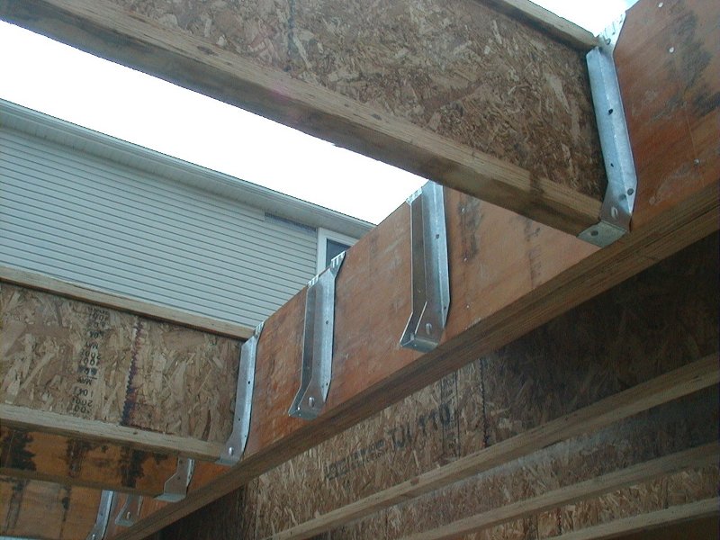
The image below shows, on
a separate job, how the floor joists are "hanged" from a plate. This
one is hanging off of another beam but the one on our house addition has
been hung on a plate attached to the concrete stem wall.
A corner of the existing
house showing the wall plate, hangers, center beam and floor joists as
well as the sandwiched insulation.
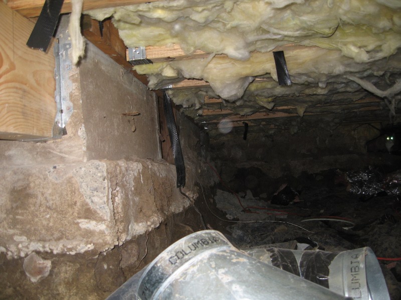
An image of the same space
looking to the right of the image above.

The inside of this space
showing the interior walls (2x4 construction, 3-1/2" wide) and exterior
walls with sheathing (2x6 construction, 5-1/2" wide). The sheathing
(1/2" plywood or OSB) is on the outside of the "Core Face: Exterior" plane
and before the "Finish Face: Exterior" plane so it is on the outside of
the exterior of the sub-floor and stem wall plane. To finish the
exterior walls you would add a layer for the dimensionless wind barrier
on the outside of the sheathing and then siding. On the inside of
the "Core face: Exterior" you would add the structure (2x6) and 1/2" drywall.
Occupying the same space as the structure of the wall (the 2x6) would be
the insulation. The interior wall sandwich would be 1/2" drywall-structure-
1/2" drywall, making the wall 4-1/2" thick.

|
- |
|
|
 |
|
-
Week
4:
No class
on Tuesday due to my attendance at SolidWorks World.
What
is due: Modifications to your "Dream House". |
Provide
to me your "Dream House" model assignment by Friday at 5pm. |
|
- |
|
|
 |
|
-
Week
5:
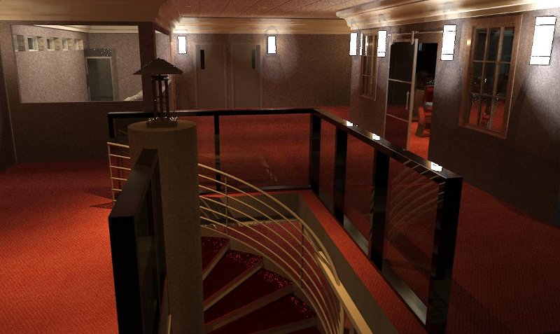
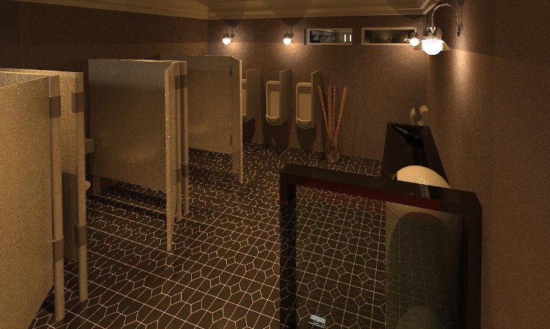
| What
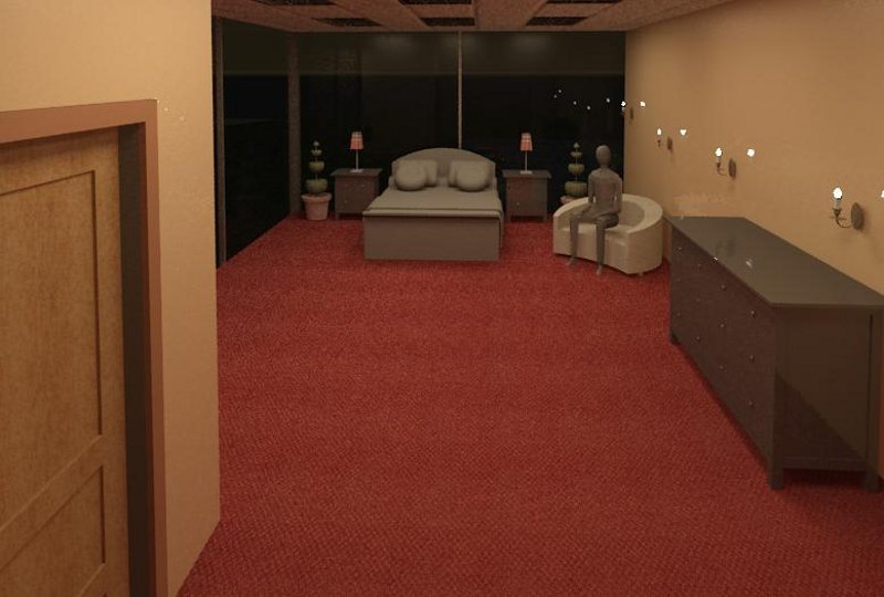
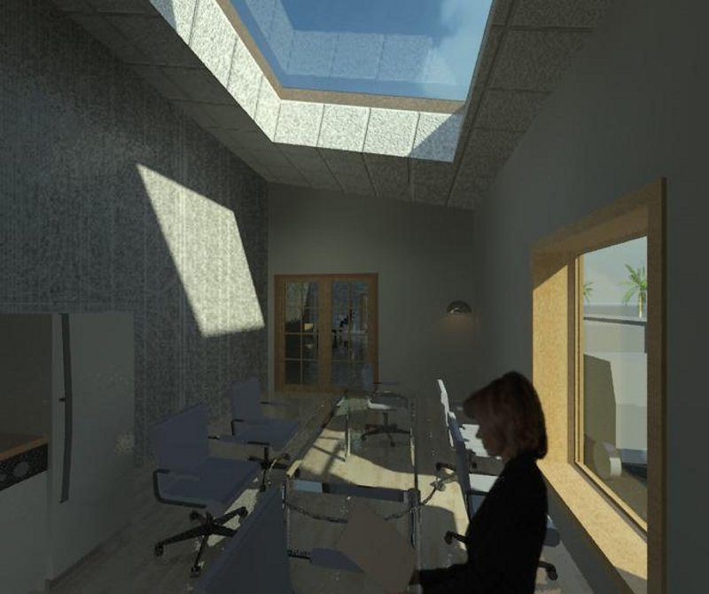
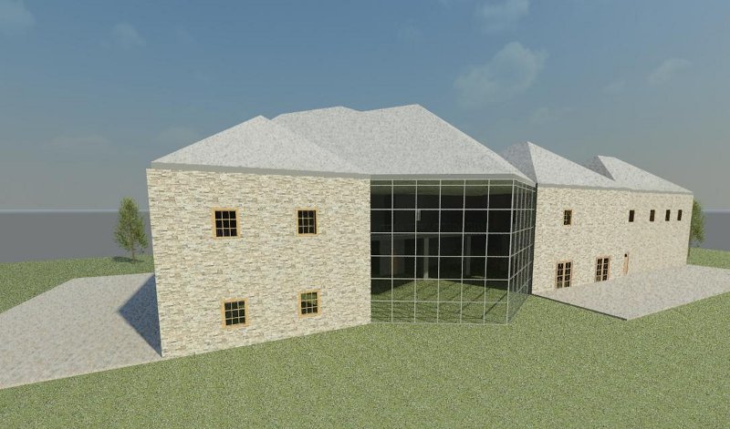
is due: A rendering of your house and an animated Walk Through.
Redos from last week. |
Provide
4 different renderings of your house with various settings and provide
videos of your Walk Throughs. Hand in by 5pm via email or flash drive
in the lab. |
Render your house using Chapter
9 as a guide.
-
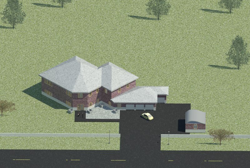
Include your site plan
-
Include various external site
plan components
-
Provide 4 different renderings
from various views
-
Use various settings including
camera elevation
-
Use as high of a resolution
as practical
-
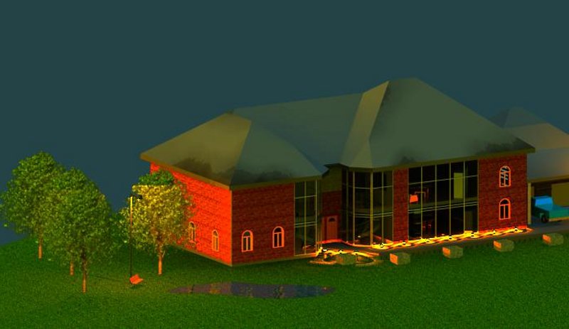
Adjust exposure settings to
achieve an attractive image
-
Save to project
-
Save to an external file as
a *.png image.
-
Hand your project and images
by 5pm via email or flash drive in the box.
-
Add lighting and render on the
inside for extra credit.
Provide 2 Walk Throughs your
house using Chapter 9 as a guide.
-
Include your site plan
-
Include various external site
plan components
-
Cover both floors
-
Walk through most of the rooms
on each floor
-
Do not walk through walls only
through doors
-
Hand your project and videos
if possible by 5pm via email or flash drive in the box.
|
- |
|
|
 |
|
-
Week
6:
Exam
on Tuesday,
What
is due: Correct your exam. |
|
Exam on Tuesday (2.5 hours)
and will include:
-
A written test at the beginning
of the class consisting of short answer, true and false and multiple choice
questions. Closed book, no external audio devices.
-
Design assignment will follow
the written test and will consist of a simple project including some of
the modeling methods discussed in Chapters 1 through 5. You will
have until 6:30 to complete and provide this file via a flash drive (10%
off for each 10 minute intervals after 6:30 that this file is late) Closed
book, no external audio devices.
-
The following are some last
minute tips on the design assignment portion of the examination:
-
The first floor will have the
following rooms: Living, Dining, Kitchen, Bath, Office and Utility.
-
The Second Floor will have the
following rooms: Master Bed, Master Bath, Bedroom1, Bedroom 2 and Bathroom
-
Know how to do a wall "Reveal"
-
Know how to modify an exterior
wall to include an angled wall and to "Edit Boundary" of the exiting ceilings
and floors.
This week's design assignment
: Correct the design portion of your exam and hand in your exam file and
markups to me or in the box by 5pm on Friday.
We will start a new project
for next week to be handed in as a sheet set next Friday. The project
will be guided by the following:
-
Commercial project of your choice
-
Think about what you would like
to model and design, some examples may include a restaurant, store (convenience,
donut, coffee, music, video, book, comic book, toy, etc...), office building
(2 or more stories for 2 people), apartment building (2 or more stories
for 2 people).
-
Make your choice today in class
-
Requirements include:
-
public area with furniture,
reception or transaction area, office cubicles or commercial displays or
kitchen, rest rooms, break room or office.
-
Custom wall types specific to
your project (do not use the Stacked Wall).
-
More requirements to follow
next week.
|
- |
|
|
 |
|
-
Week
7:
| What
is due: Sheet Set and Commercial Project Model |
Read the
rest of Chapter 14 on Setting Up Sheets. Skip the part about Revision
Tables and creating DXF files. Start to read Chapter 6 followed by
7. |
For your weekly design assignment
you will be graded on 4 items. Details follow below, click on the
following links:
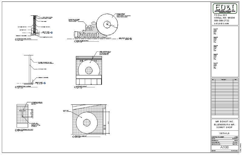
Logo
-
Design a logo for your title
block. Choose a name and style that fits your career ambitions or
personality. You may design something in Revit, AutoCAD or another
image program. Use the following criteria:
-
Your logo must be unique
-
An image file
-
Inserted where the Revit logo
is on the Titleblock template
-
Does not have to look 3D
-
Include your name or a company
name
-
Include some graphical styling
Consider some design
ideas that you can find on the web. Below are some images of some
AutoCAD files of logos from some companies that I have worked with in the
past. Also check out my previous class for previous student logo
designs at:
IET-161-Fall2010
Titleblock
-
Create a titleblock from the
Revit titleblock template file that we worked on in class on Tuesday with
all of the elements discussed including the parametric links.
-
Include a company address, phone
number and website address below, nearby or included in your logo.
Sheets
-
Create a Sheet Set of your commercial
project with all of the elements, including the parametric links,
that we discussed and practiced in class on Tuesday and explained in Chapter
14.
-
Follow the guidance provided
at the Student Resource
link in the menu section above.
-
Print 1/2 sized drawings (11x17)
of the following views
-
First Floor Plan
-
Second Floor Plan (if any)
-
The 4 standard Elevations
-
Two elevations can share the
same sheet if there is room
-
2 Sections perpendicular to
each other
-
The two sections can share a
sheet if there is room
-
Provide dimensions, annotations
and details as directed in class this Thursday
-
Each floor plan to contain at
least 10 dimensions showing the location of pertinent features
-
Whole unit dimensions for the
exterior dimensions for the length and width of your building
-
Each of the elevations needs
to have at least 6 dimensions (or all of the dimensions that are relevant
to that view)
-
These dimensions need to be
relevant to that view such as items vertically oriented.
-
Staple all of the drawings in
order with the fastener in the upper left corner.
Put these in the box
by
5pm on Friday.
Model
-
Email, link, transfer, or provide
a flash drive of your model in the box by 5pm on Friday. You will
be
graded on the following typical building components for a preliminary building
model including:
-
Exterior walls
-
Interior walls
-
First floor, building pad or
slab
-
Doors and windows
-
Ceiling(s)
-
Roof(s)
The model does not have to be
complete except for what is listed above. Include the building features
as listed from the previous week. You do not have to have a Site
Plan or components but these will be considered as extra credit if included
(only if they are appropriate to the model). Extra credit will also
be applied toward any unique modeling techniques which may include, but
is not limited to, signage, decals and lighting. If demonstrated,
this credit will be an equivalent grade to a design assignment. See
me if you have some ideas.
|
- |
|
|
 |
|
-
Week
8:
| What
is due: Sheet Set and Commercial Project model incorporating the updates
from last weeks markups. |
Read
Chapters 11 and 12 before class on Thursday. We will be incorporating
some of the elements from these chapters into your sheet set. |
Sheets
-
Modify your Sheet Set from last
week incorporating the updates from your markups from last week.
-
Use last week's list for guidance.
-
Also, like last week, follow
the guidance provided at the Student
Resource link in the menu section above.
-
Print, in color, 1/2 sized drawings
(11x17) of the following views
-
Cover sheet with (see image
examples below)
-
Project Title
-
Project Owner
-
Project address
-
Photo real rendering of an isometric
view of your model (most prominent feature on the sheet)
-
Sheet list schedule
-
Project team information (your
information)
-
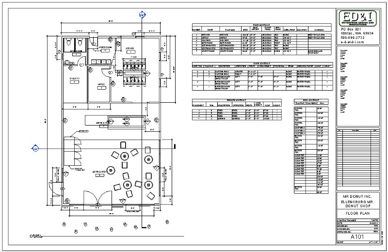
First Floor Plan (see image
example below)
-
Include a Room Schedule on the
sheet per Chapter 11
-
Include door and window tags
per Chapter 12
-
Include door and window schedules
per Chapter 12
-
Hint: to get a numbered tag
to show in a schedule (such as a window and door tag) you must chose the
field "Mark", the "Type Mark" field is a door category number that Revit
assigns the door or window as you model and is not part of the tag.
-
Provide schedules, dimensions,
annotations and details as directed in class this Thursday
-
Each floor plan to contain at
least 10 dimensions showing the location of pertinent features
-
Whole unit dimensions for the
exterior dimensions for the length and width of your building
-
Dimensions of door and window
widths
-
Dimensions of door and window
locations
-
Staple all of the drawings in
order with the fastener in the upper left corner.
Put these in the box
by
5pm on Friday.
Model
-
Email, link, transfer, or provide
a flash drive of your model in the box by 5pm on Friday. You will
be graded on the following typical building components for a preliminary
building model like last week including:
-
Exterior walls
-
Interior walls
-
Bounded rooms with names and
numbers
-
First floor, building pad or
slab
-
Doors and windows with tags
-
Ceiling(s)
-
Roof(s)
-
Site Plan with components (at
least 4 different types)
-
Building components (add at
least 8, lights, chairs, cars, counter tops, sinks, etc...)
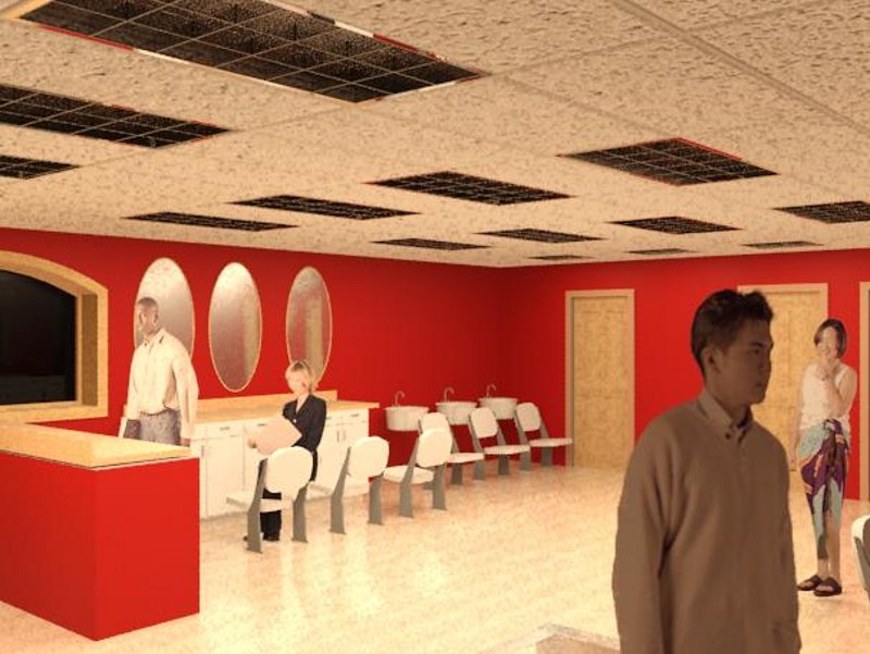
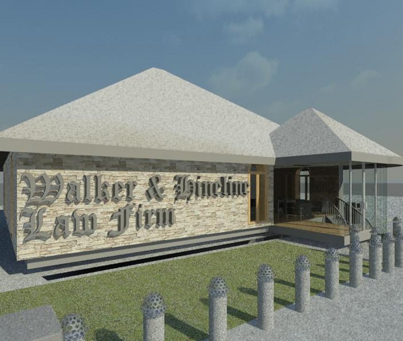
-
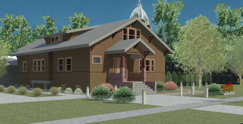
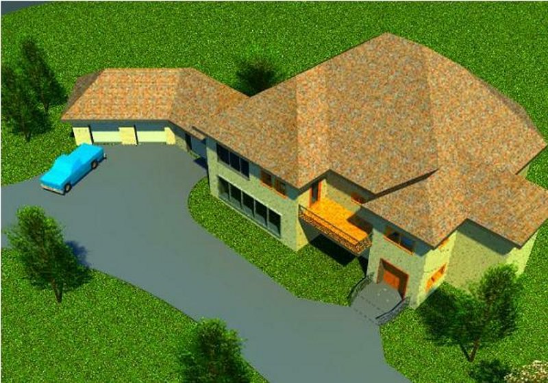
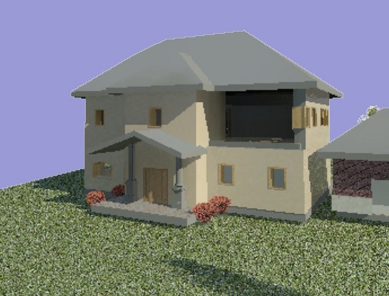
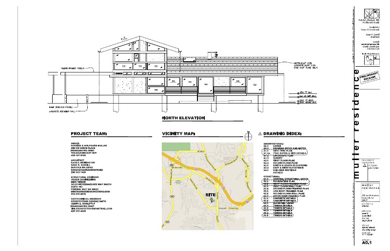
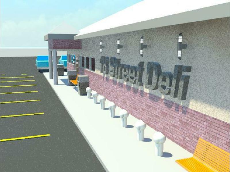
Examples of some cover sheets
 -
-
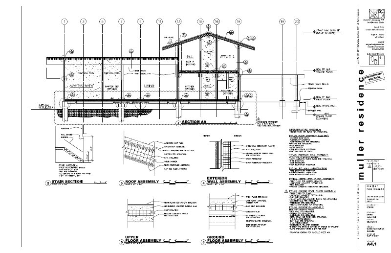
Another sample project of
a house to be built in Issaquah
 -
-
Floor plan example with
wall, door, window and room tags with the associated schedules.
|
- |
|
|
 |
|
-
Week
9:
| What
is due: Presentation feedback forms, Commercial Project model and sheet
updates. |
Exam on
Tuesday, Preliminary project presentations on Thursday. Read ahead
Chapters 12 and 13. |
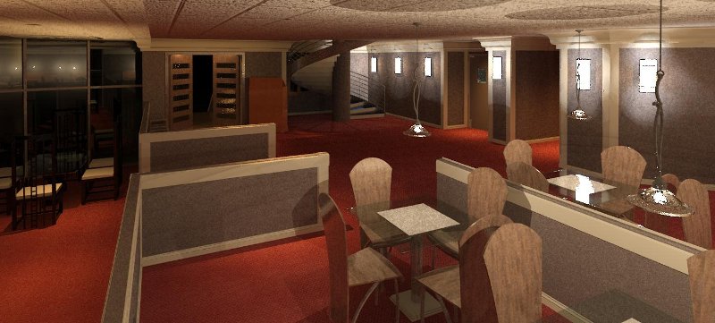
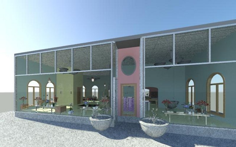
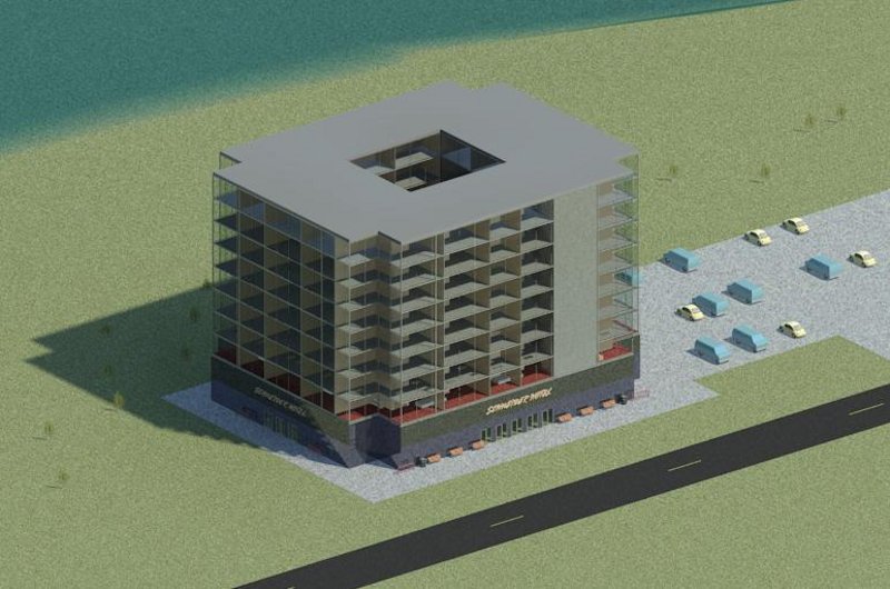
Commercial Project presentations
on Thursday. Use the following guidelines for your presentations:
-
Introduction, provide your name,
major and class position (senior, junior, etc...)
-
Introduction to your project,
project name and service provided
-
Tour, start with a 3D view then
the floor plan. Since these are all commercial projects the design
facilitates the interaction between customers and hired staff.
-
Show how a customer will approach
the building (street and parking).
-
Show how a customer will enter
the building and interact with staff.
-
Show and explain the service
area.
-
Show the support areas
-
Show auxiliary areas
-
Move on through the model and
demonstrate the following:
-
Ceiling plan showing what kind
of ceiling is used (you may have to go to a section view)
-
The 4 elevations and the features
associated with them.
-
The 2 sections, or more, detailing
some of the internal features of your project
-
Show the wall types
-
Show the floor types
-
Show the doors and types
-
Show components used and where
they came from
-
3D view, explore the outside
of the building and grounds
-
Show some renderings
-
Show a walk through
-
Describe a modeling technique
unique to what has been demonstrated in class so far (save this part for
the final).
-
Conclusion:
-
Summary
-
Ask for questions
-
Ask for suggestions i.e. "how
can I model this differently or better"
I would invite interaction and
would encourage raising your hand to interrupt for explanation or to share
a different technique.
Keep your presentation to
no more than 10 minutes
Evaluation feedback forms
will be handed out at the beginning of the class
-
Sign your name on the cover
only
-
Fill in the student's name,
on each page in the book, in the space provided
Provide ample suggestions
and constructive comments
Hand in the following for
evaluation this week:
Model
-
Email, link, transfer, or provide
a flash drive of your model in the box by 5pm on Friday. You will
be graded on the following typical building components for a preliminary
building model like the previous weeks' assignments including:
-
Exterior and interior walls
with tags
-
Bounded rooms with names and
numbers
-
First floor
-
Doors and windows with tags
-
Ceiling(s) with lights, similar
to the recent examination
-
Roof(s)
-
Site Plan with property line
and components (at least 10 different types)
-
Building components (add at
least 10, lights, chairs, cars, counter tops, sinks, etc...)
Sheet, Modify your Sheet Set
from last week incorporating the updates from your markups from last week
and from the exam.
-
Read Chapter 12 and use last
week's information above for guidance.
-
Also, like the last couple of
weeks, follow the guidance provided at the Student
Resource link in the menu section above.
-
Print, in color, 1/2 sized drawings
(11x17) of the following views
-
First Floor Plan
-
Revise your Room Schedule to
include the following:
-
Fields shall be in order: Number,
Name, Perimeter, Area, Base Finish, Floor Finish, Wall Finish, Ceiling
Finish, Department and Comments.
-
Place and organize this schedule
per your recent markups, make it look good.
-
Center the number column
-
Revise your door and window
schedules per last week. Hint: to get a numbered tag to show in a
schedule (such as a window and door tag) you must chose the field "Mark",
the "Type Mark" field is a door category number that Revit assigns the
door or window as you model and is not part of the tag.
-
Door fields shall be in order:
Door Tag (Mark), Type Mark, Description, Operation, Width, Height, Thickness,
Head Height, Manufacturer, Model, Cost.
-
Window fields shall be in order:
Window Tag (Mark), Type Mark, Description, Operation, Width, Height, Head
Height, Manufacturer, Model, Cost.
-
Wall Schedule, add wall tags
and a wall schedule, with the following fields in order: Wall Tag (Type
Mark), Family and Type, Fire Rating, Length, Width, Area.
-
Make the tag names short and
abbreviated
-
The Family and Type values do
not need to be capitalized.
-
General notes on schedules
-
Make up values for any unknown
fields
-
CAPITALS unless noted otherwise
-
Spread out the fields so that
words are not chopped up.
-
Make it look good.
-
Line up schedules to each other
so they are aligned with each other
-
Create a new sheet, numbered
after your floor plan sheet, if you need more room.
-
Extra credit for changing the
appearance of your schedules, they all must look the similar.
-
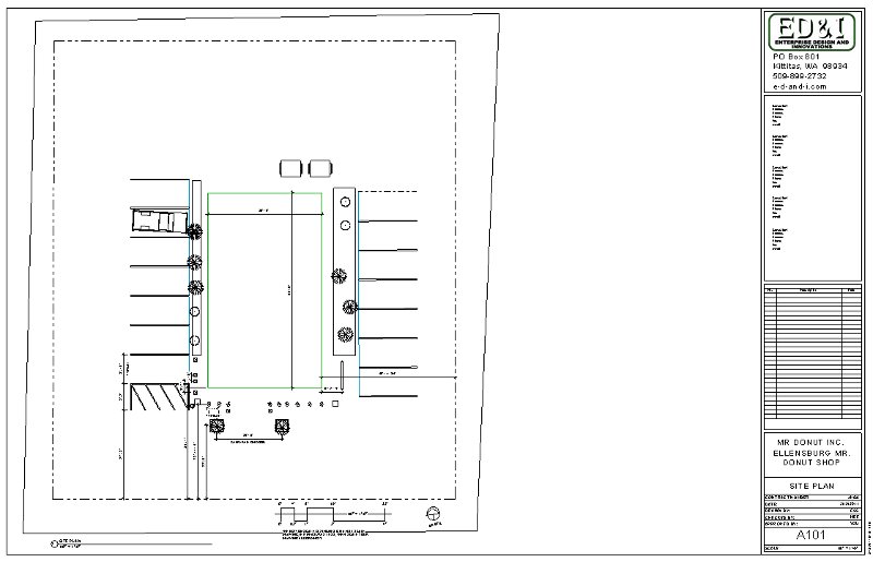
Preliminary Site Plan
-
Number this before your Floor
Plan
-
Add site plan related dimensions
-
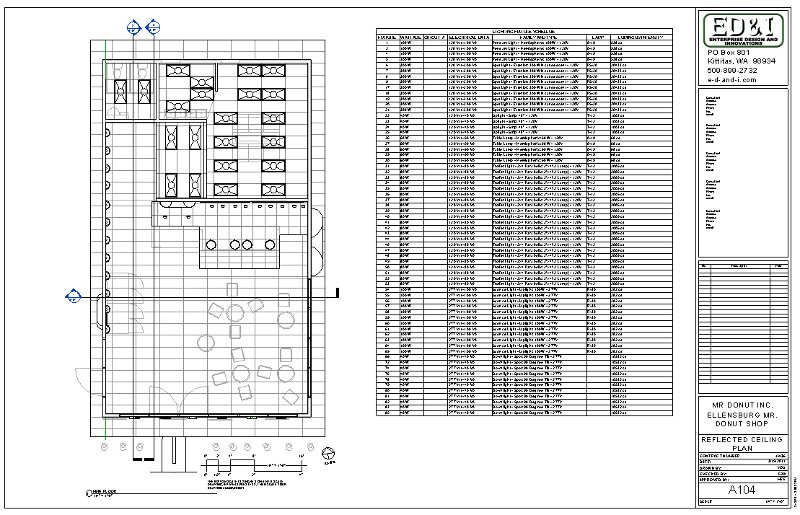
Preliminary Reflected Ceiling
Plan
-
Number this after your Floor
Plan
You will be graded on the following
this week as described above
Titleblock, Site Plan, Floor
Plan, Reflected Ceiling Plan, Model
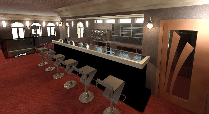
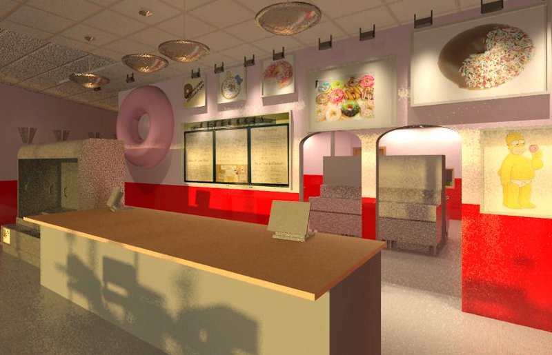
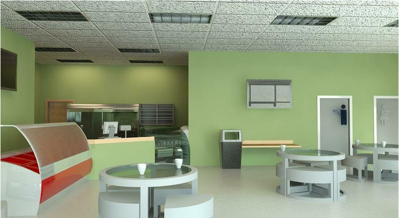
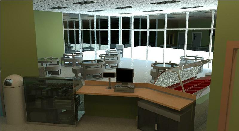
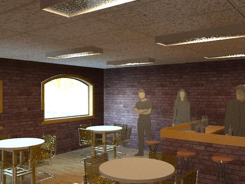
Extra Credit: This week
only, provide a photo real rendering of the interior of your exam coffee
shop using a camera view, medium or high resolution, include various components
and light fixtures. The more components included the more points.
Exam guidance:
What is a datum?
Think about a coffee shop.
Insert Troffer lights, Parabolic,
12 to 15 in the Seating and Serving areas, locked to the ceiling grids.
Know how to create a custom
wall type, including adding paint with color
Know how to modify the material
"Ceramic Tile" to change the color from blue to what ever color you want
(Hint: Manage, Materials, (duplicate and modify "Ceramic Tile - 4" Blue")
Render Appearance tab, Ceramic section, right click in the image box and
choose color).
|
- |
|
|
 |
|
-
Week
10:
| What
is due: Redos from last week, Commercial Project renderings. |
Read and
practice Chapter 13 |
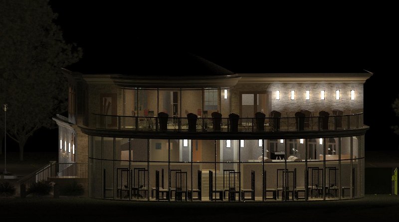
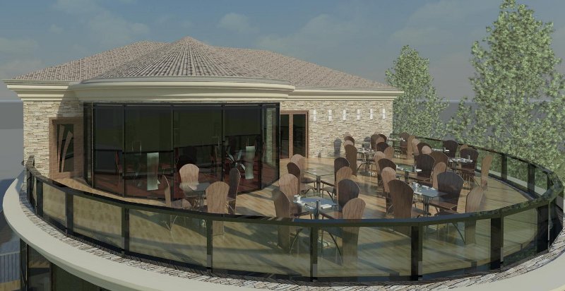
Assignments, For this week
only:
-
Image renderings. Provide
renderings of the interior and exterior of your project, various settings
from various angles, medium resolution or better, include your best rendering
for your cover page. send by 5pm on Friday.
-
Walk throughs. Provide
a walk through of your building per settings suggested in past assignments.
|
- |
|
|
 |
|
-
Final:
| Final
Project due on Thursday. |
Final project
Presentations on Thursday along with your drawings and model. |
The following is what is
due on Thursday for your Final Project evaluation.
Presentation
-
Use the guidance provided in
the Week 9 section above
Sheets
-
Make certain that you understand
your markups and incorporate them into your Final Project drawings.
-
A list of all of your Final
Project drawing sheets, that will be required for evaluation, are listed
below.
-
Number them in ascending order
-
Incorporate all of the elements
for these sheets as required from the previous weeks' descriptions.
-
Also include into your drawings
what is listed below.
-
Sheet List:
-
Cover Sheet
-
Site Plan
-
Hide your roof to reveal your
walls
-
Hide other non relevant non
site plan building features for extra credit
-
North Arrow
-
Extra credit for a modified
or unique one
-
Orient the arrow off center,
consistent orientation and location on all plan sheets
-
Graphic Scale (Scale Bar), choose
the correct size
-
extra credit for a modified
or unique one.
-
Floor Plan, include the following
from the list below. If the items in the list do not fit on the floor
plan sheet then move them to a Schedules sheet. The items listed
below are in order of importance so move the bottom items first to the
new sheet. Keep the Door, Window and Wall Schedules together.
The Schedules sheet is numbered after the floor plan sheet.
-
North Arrow
-
Graphic Scale (Scale Bar)
-
Door Legend for plan symbols
-
Window Legend for plan symbols
-
Room Schedule
-
Door Schedule
-
Window Schedule
-
Wall Schedule
-
Schedules (if not included on
your floor plan sheet)
-
Reflected Ceiling Plan
-
North Arrow
-
Graphic Scale (Scale Bar)
-
Lighting Fixture Schedule with
the following fields in order: Fixture (Mark), Wattage, Circuit # (leave
this blank), Electrical Data, Family and Type, Lamp, Luminous Intensity.
-
Center the Fixture column
-
Use a new sheet(s) if you need
more room, name the sheet "Lighting Fixture Schedule"
-
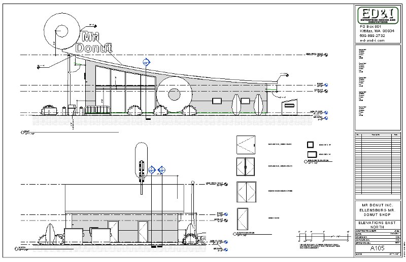
Elevations, 2 or 4 sheets
-
Elevation related dimensions
-
Graphic Scale (Scale Bar)
-
Door Legend for elevations
-
Window Legend for elevations
-
Sections, 1 or 2 sheets
-
Section related dimensions
-
Graphic Scale (Scale Bar)
-
Details
-
Provide at least 6 details
-
Must have annotation callouts
with leaders
-
3/32" text size, Arial, CAPITAL
lettering
-
Insert break lines
-
Show one example of a 2D filled
region per Chapter 13
-
One section detail of an exterior
wall with insulation
-
One section detail of an interior
wall
-
Print your sheets, have these
printed before the Final on Tuesday
-
Print out all sheets 1/2 size,
staple in upper left corner
-
Print out 3 full size sheets
-
Cover Page, First Floor Floor
Plan and one of your Elevations sheets (choose the one with more detail)
-
Print on the HP800 plotter,
choose the following settings
-
Put in the full sized paper
roll, 42"
-
Lanscape orientation
-
Choose ANSI D oversize (the
regular ANSI D size will cut off your borders)
-
Center the plot
-
Zoom to 100%
-
Call or email if problems
-
Make certain your sheets scale
correctly, each sheet will need to be trimmed after printing (I can do
this on Thursday).
Model
-
Follow the guidelines from previous
weeks plus the following:
-
Update your model per your peer
evaluations
-
Add a custom floor
-
The more custom items and appropriate
components the more extra credit you will get.
-
Below are some examples
of some of the sheets in my sheet set. Yours should emulate this
format or something similar.


-
Example of details on a
section view sheet, click on the image below for the full pdf document.
-
Regarding the
creation of Revit Families:
The images below display
some of the dimensions associated with the construction of doors and windows.
We will not be covering the construction of Revit families but if you want
to pursue it on your own you may find the information and images below
useful. If you want to explore Chapter 17 you can use the information
below to help modify the existing families provided by Revit or to create
new ones.
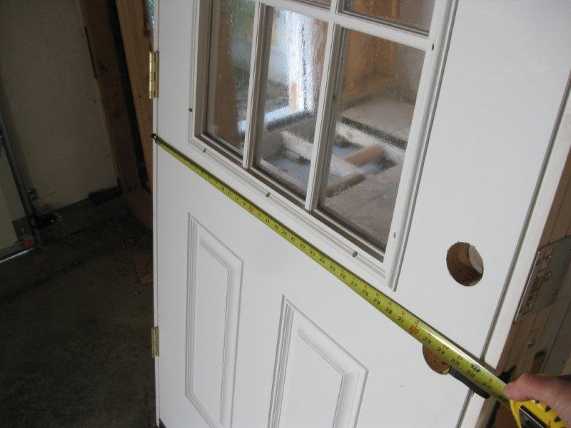
-
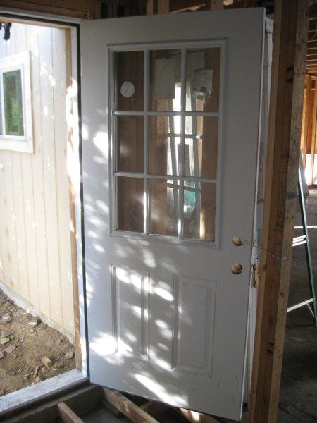
The immediate images that
follow show dimensions associated with a standard 36" door installation.
The image below is a 36" exterior door (6-1/2" exterior wall thickness).
 -
-
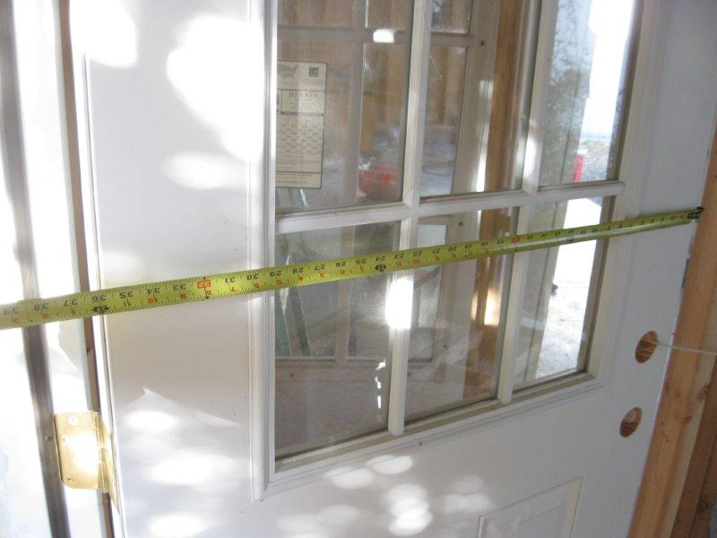
The actual door size is
35-7/8".
 -
-
The actual door size is
35-7/8" (close up).
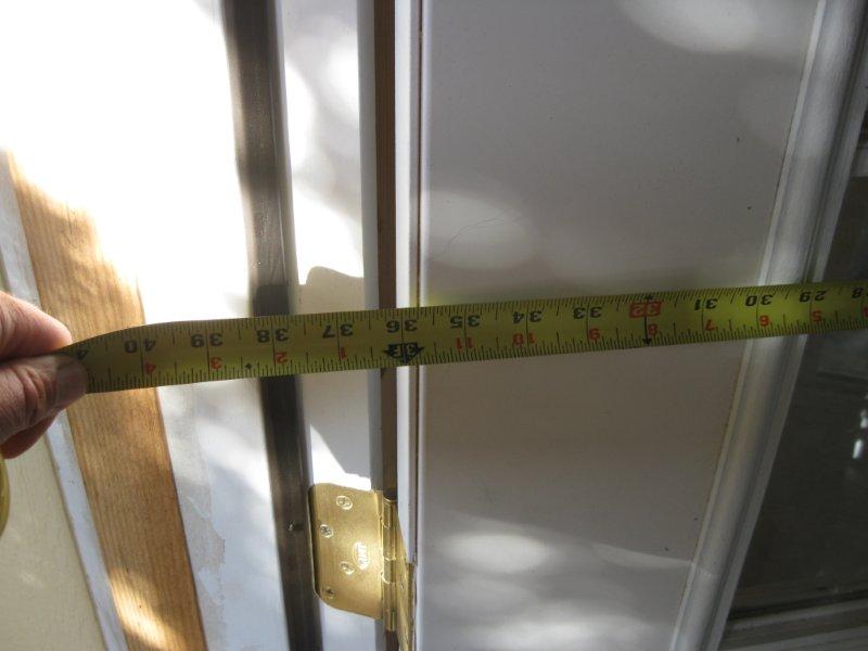 -
-
The exterior dimension size
is 40" including the exterior trim (brick mold).
 -
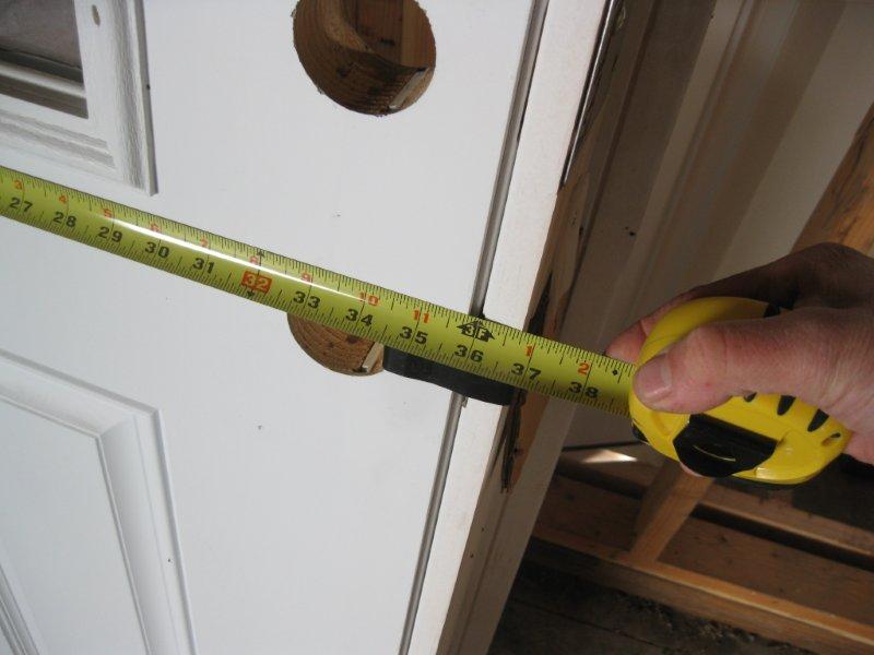
-
The actual opening of the
door, inside clearance is 36". This measurement determines the door
size.
 -
-
The actual opening of the
door, inside clearance is 36" (close up).
 -
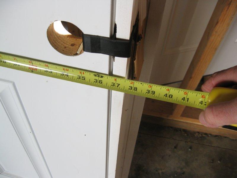
-
The door frame on the interior
of this door is 37-1/2".
 -
-
The door frame on the interior
of this door is 37-1/2" (close up). Allow for about 38" rough door
width opening. Revit will cut this out for you.
 -
-
The framed door opening.
 -
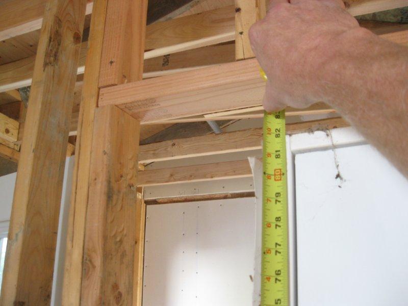
-
The framed door opening
(rough opening) height (about 81-3/4"). Allow for about 82" rough
door height opening. Revit will cut this out for you.
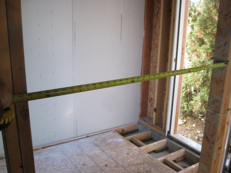
 -
-
The framed door opening
(rough opening) width.
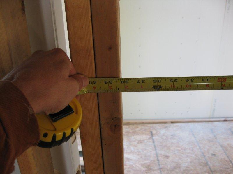
-
The framed door opening
(rough opening) width at 38-1/4" (close up) (usually 38"). This gives
us about a 3/8" on each side of the door for adjustments, using shims,
during installation.
 -
-
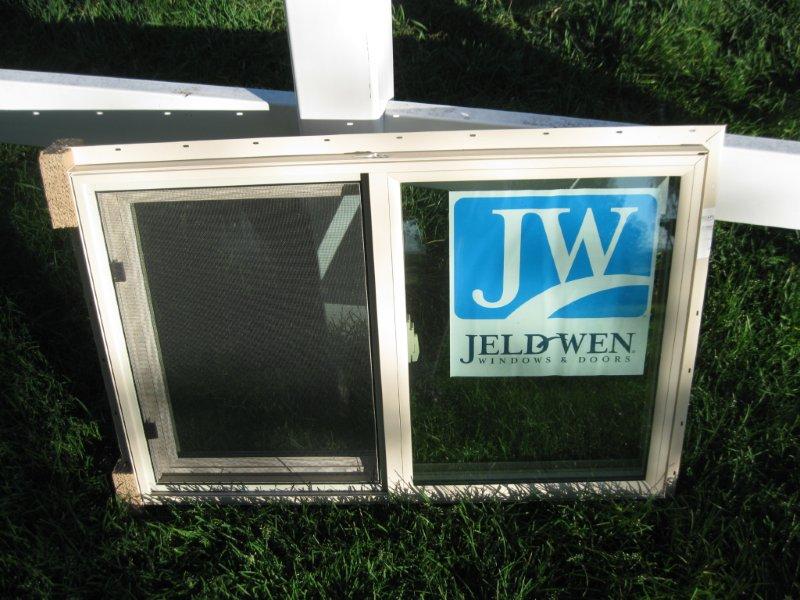
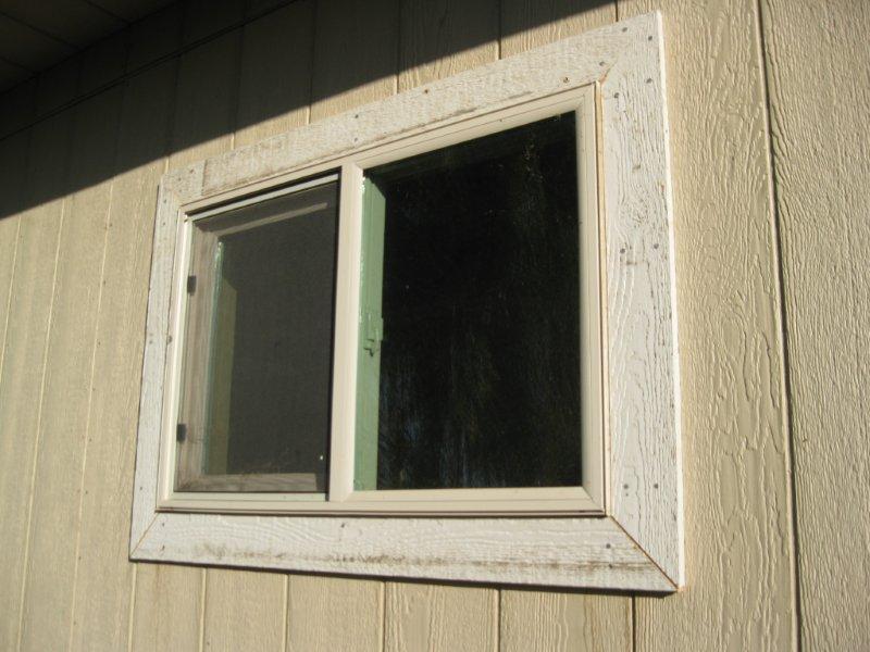
The images that follow show
dimensions associated with a standard 3' x 2' window installation. The
image below shows a framed window opening and window on the interior of
a garage for 3' x 2' window.
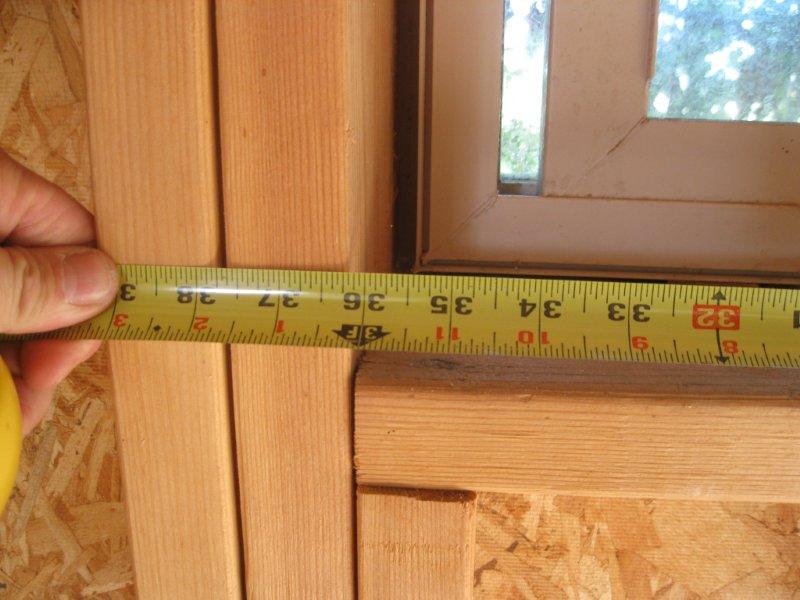
 -
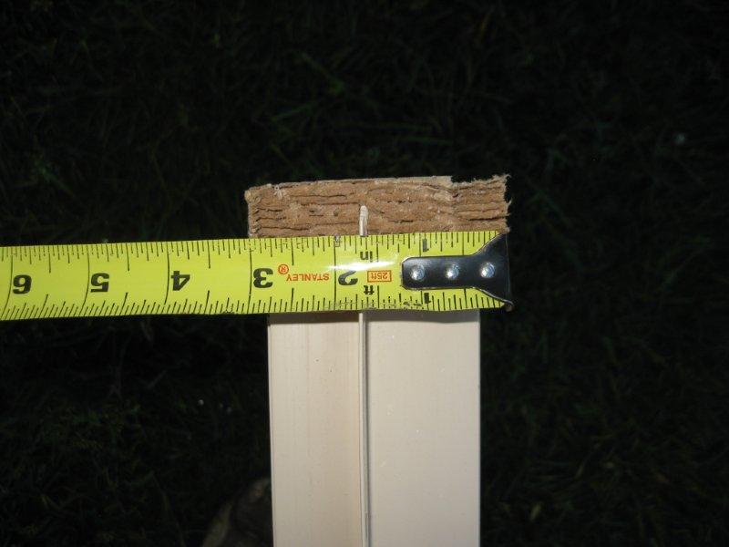
-
The framed window opening
(rough opening) for 3' x 2' window (close up). This is one of the
measurements that determine the window size.
 -
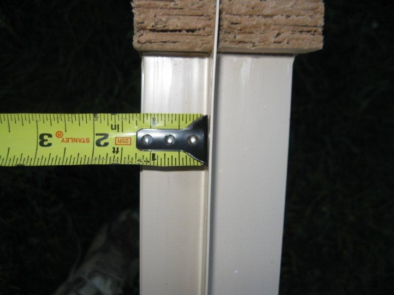
-
The framed window opening
(rough opening) for 3' x 2' window (close up). This is one of the
measurements that determine the window size.
 -
-
An uninstalled 3' x 2' window.
The window measures about a 1/2" less on each side referencing the window
size. This gives us about a quarter inch on all sides of the
window for adjustments, using shims, during installation.
 -
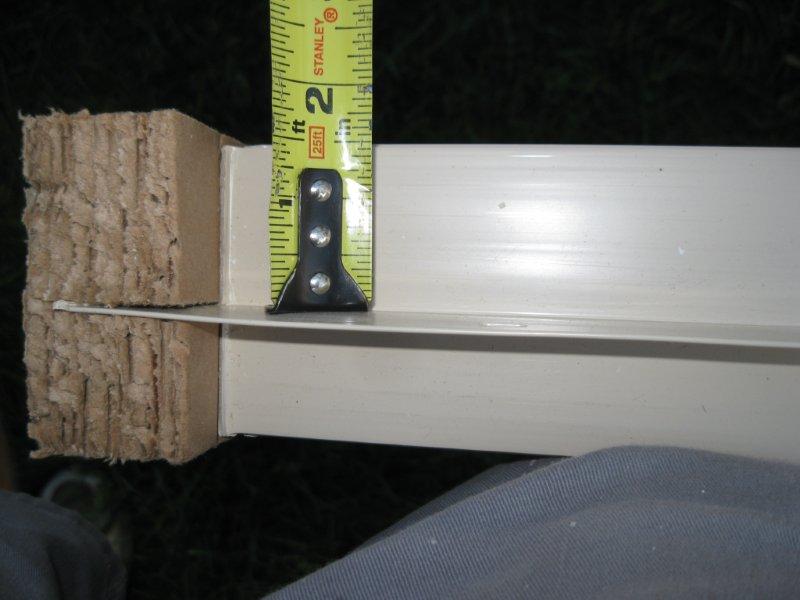
-
Window and frame is about
3" thick.
 -
-
The nailing flange is positioned
about 1" back from the exterior edge of the window.
-
The nailing flange is about
1" long.
 -
-
A finished window from the
exterior excluding caulking and paint, notice the nailing flange is covered
by the window trim.
 -
-
A finished window on the
interior with a window sill. Revit will have library windows with
the trim and window sills included.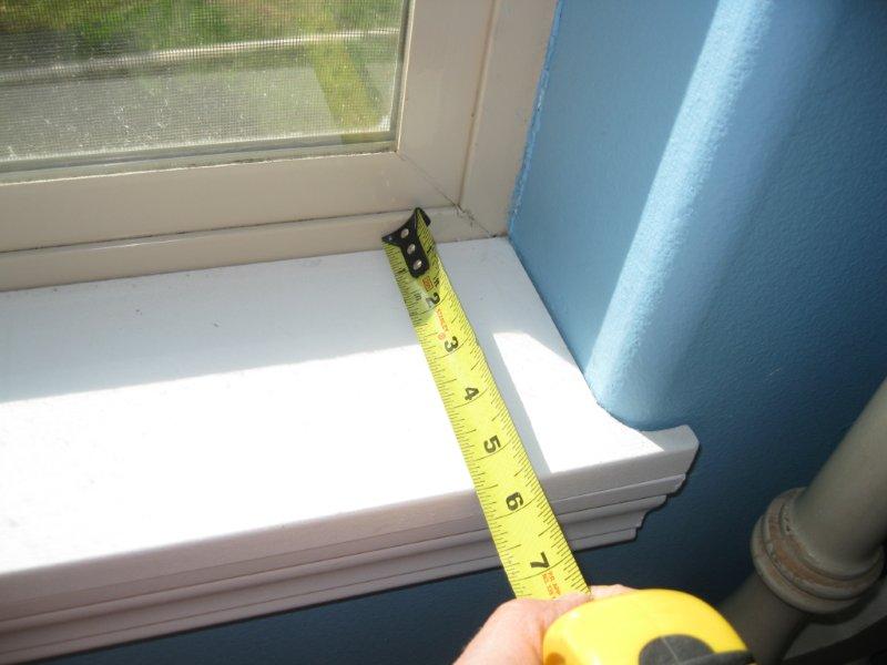
|


.jpg)