|
- |
|
|
 |
 |
-
Week
1:
| In this
section, for every week, there will be a listing of what is due for that
week. You will practice the assignments listed in this section to
prepare for the In Class Evaluation (ICE) where you demonstrate the skills
that you have learned. ICE's are usually on Tuesdays. See the
syllabus for assessment details.
Design
Assignments due this week:
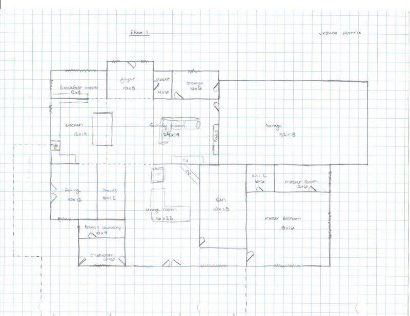
For next
Tuesday come to class with sketched floor plans of a Dream House that you
would like to design. You will be modeling this project both in AutoCAD
and Revit later in the quarter but for this assignment produce a paper
and pencil sketched drawing of both the first and second floor of a house
(refer to the Week 2 section below for more information). |
In this
section there will be additional information on what should be read, practiced
and produced
before coming to class for the week. Plus it
may contain announcements relevant for that week's class.
Announcements:
You should
have bought the following book from the Wildcat Shop, Introducing Autodesk
Revit Architecture 2012, by Patrick Davis. If you bought the
2011 version instead please return it to the bookstore and exchange it
for the 2012 version.

Read
and practice ahead:
See Week
2 for details on what should be read and practiced for Week 2.
|
Class
exercises and assignment details:
See Week 2 for details on
your Sketched Floor Plans assignment.
-
|
- |
|
|
 |
|
-
Week
2:
| Design
Assignment due:
(this
is a repeat of what was listed for Week 1) On Tuesday come to class with
sketched floor plans of a dream house that you would like to design.
You will be modeling this project both in AutoCAD and Revit later in the
quarter but for this assignment produce a paper and pencil sketched drawing
of both the first and second floor of a house. See details
below. |
Read
and practice ahead:
View
the Instructional Videos below showing how to set
up your template file and to draft the CMU drawing.
View
the following videos from the Autodesk website for AutoCAD 2012.
Download,
view, print (if you like), read and practice the first three tutorials
from the Autodesk website for AutoCAD 2012 (apparently these are the same
as the 2011 versions). Download and then unzip the downloaded files
on your flash drive or network save location:
You may
also download Tutorials 4 and 5 if you like for use next week to save time.
AutoCAD
has various training aids that you may also find useful. A link to
the Autodesk website with these tools are available at the following link
(we will cover only a few of these in this class as listed above):
|
Class
exercises and assignment details:
Sketched Floor Plans Assignment:
Your sketched floor plan
will be graded on the following criteria, Click
here for your ICE grading criteria. Download and print out the
grading criteria before class on Tuesday, sign your name, fill in the date,
staple it to your assignment and hand in all of the related documents at
the instructor's desk.
For this and all assignments
your work has to be original and unique or you will get no points!!
For your sketched floor plans,
put some thought into this project.
-
Before starting, spend
some quality time looking at and studying homes and home
designs and consider what features you both like and dislike about them
both inside and out. Resources for this may include:
-
websites,
magazines, videos and television programs
-
new or
existing homes being built in your area that you can visit
-
Ideas
from your family's home or homes of friends and relatives
-
Consider
the following when laying out your floor plans for your Dream House:
-
Bathroom
locations should be such so that the occupants of the room will not be
visible in an adjacent room when the bathroom door is open. Perhaps
locate the bathroom in a hallway.
-
The kitchen
should be close to the front door and entry from the garage. The
kitchen is considered a destination or departure point when entering or
leaving the house.
-
Bedrooms
are peripheral elements in quiet areas of the house away from busy rooms
-
Consider
a mudroom adjacent to the front door, backdoor or garage. A mudroom
serves as a transitional room to put on or remove coats and shoes.
It also serves as a stop for outside air entering the house when the exterior
door is opened.
-
Think
about the flow of foot traffic in the house: Does it make sense?
Do you have to go through a room to get to another room? and similar thoughts.
-
You will refer to these sketches
in a few weeks and will use them to generate your computer models in both
AutoCAD and Revit.
-
Try not to make it too big,
it may end up costing you more time than is needed later in the quarter.
Requirements for your first
and second floor sketches.
-
ANSI A size sheets (8-1/2" by
11") one sheet per floor, landscape orientation
-
Draw the first floor first
-
Draw the second floor so that
it is on top and lined up with the first floor when the sheets are together
-
Area for stairs on both sheets
-
No scaling
-
No wall thickness necessary
-
use a single line to denote
interior and exterior walls
-
Label all rooms with room names
-
At least 8 rooms per floor (not
including closets)
-
3 bedrooms at least
-
Include all rooms that would
be appropriate for a house of this size including a mechanical (utility)
room, laundry room(s), entry way or mudroom(s) and office
-
Proportioned rooms
-
Example, don't make a bedroom
3 times the size of the living room, make the bedroom big enough for a
bed and the typical furniture
-
Front and back doors at least
-
Windows
-
Include a garage, attached or
detached (not considered a room)
-
Neat, thoughtful design, not
rushed
-
The erasing and moving of walls
and similar features is part of the iterative process and is expected
Items that can only appear
once or are required to appear only once will be given credit on both floors
Extras may include landscaping,
decks, furniture, fixtures, etc...
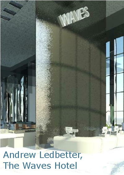
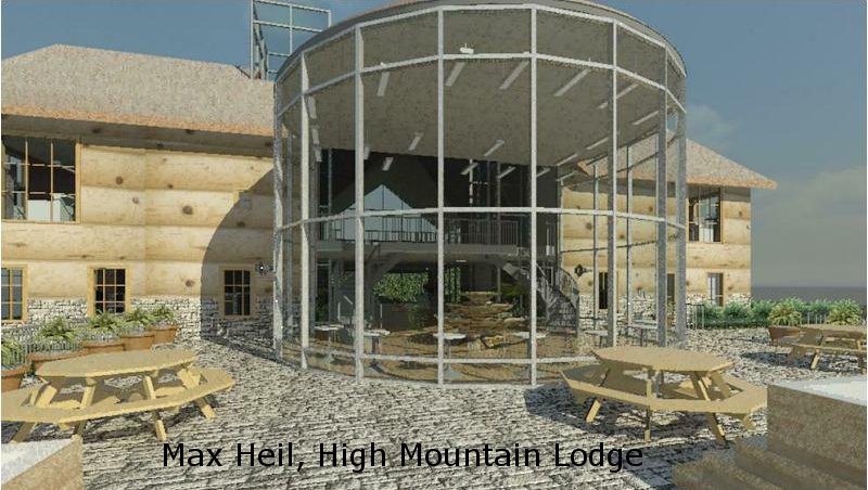
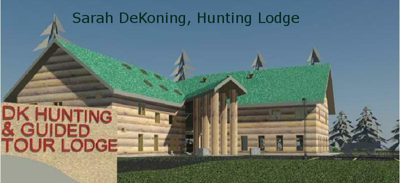
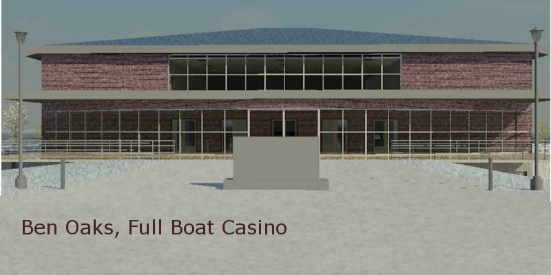
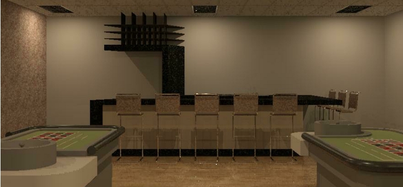
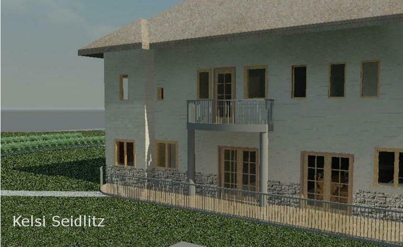
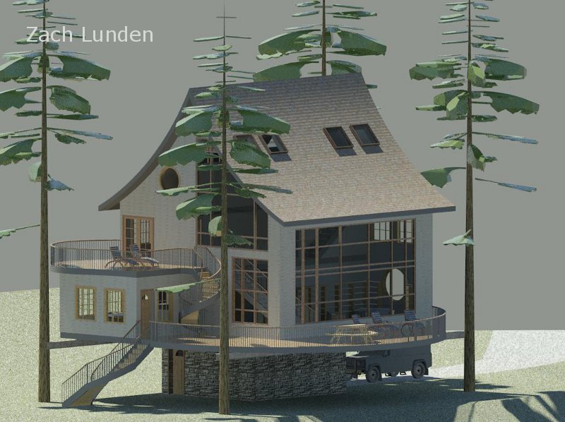
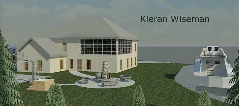
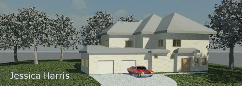
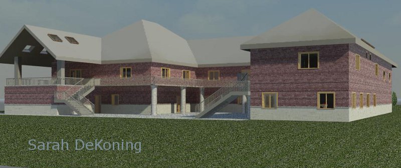
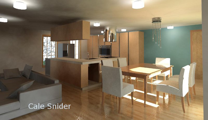
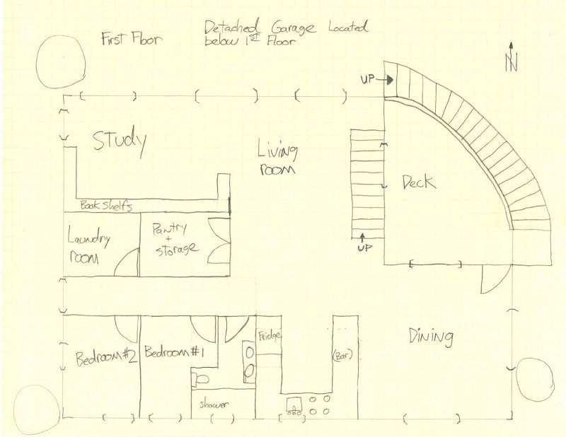
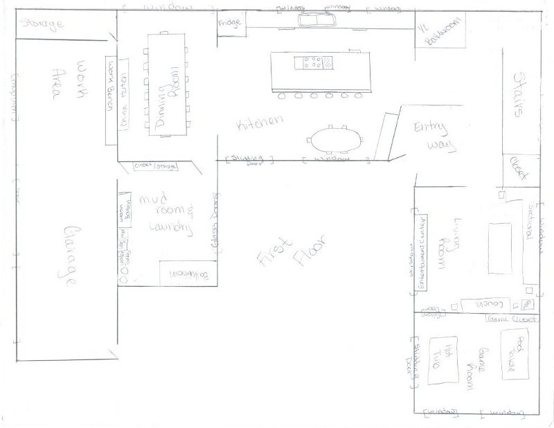
Below are some examples what
I believe to be very descriptive floor plan sketches from this class

Class
exercise:
Click
on the following link and extract this file for the AutoCAD files that
will be used as a demonstration in class on Tuesday.
110927-Gray-Osborne-Raymond-South-Bend.zip
Instructional
Videos:
View
the instructional videos at this link AutoCAD
Getting Started and Drafting regarding the subjects listed below on
how to set up your new drawing template and how to create your first drawing
of the Concrete Masonry Unit (CMU):
1.
How to change some of the AutoCAD settings for the CAD lab computers
2.
Opening AutoCAD and some basics of Paper and Model Space
3.
Opening and modifying an AutoCAD titleblock template file
4.
Modifying our Paper Space portion of the titleblock template file
5.
Modifying our titleblock in our titleblock template file
6.
More on modifying our titleblock in our titleblock template file
7.
Modifying our Title Block for an "A" sized paper
8.
More on modifying our titleblock for an "A" sized paper
9.
Finishing our Title Block for an "A" sized paper
10.
Drafting a simple object
11.
More on drafting a simple object
12.
More on drafting a simple object, updating the title block and printing
Part 1
13.
More on drafting a simple object, updating the title block and printing
Part 2
Out
of class exercises:
Practice
and produce the following exercises on your new template file with the
appropriate title block updates as described in class and on the videos
above. One of these exercises will be due at the time of the ICE
at the beginning of class on Tuesday in Week 3. Instructional videos
are available for the exercises below except for the CMU and the Elevation
(both done in class) and the Car which, if you have gotten that far, you
should already know how to do.
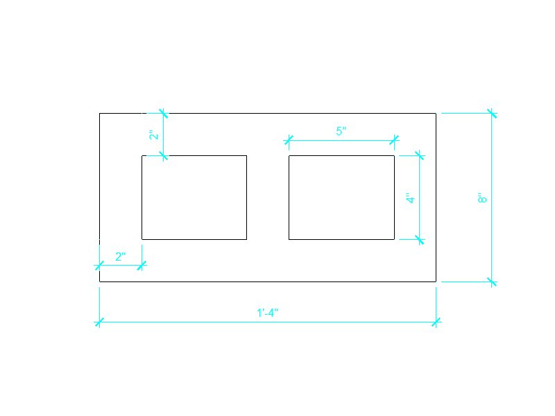
TOY
HOUSE
(click
here for link to "How To" video)
14.
How to draft the "Toy House"
CONCRETE
MASONRY UNIT (CMU)
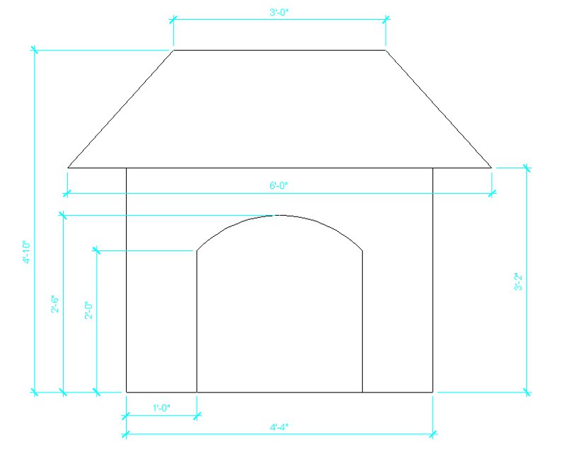
DOG
HOUSE
(click
here for link to "How To" video)
15.
How to draft the "Dog House"
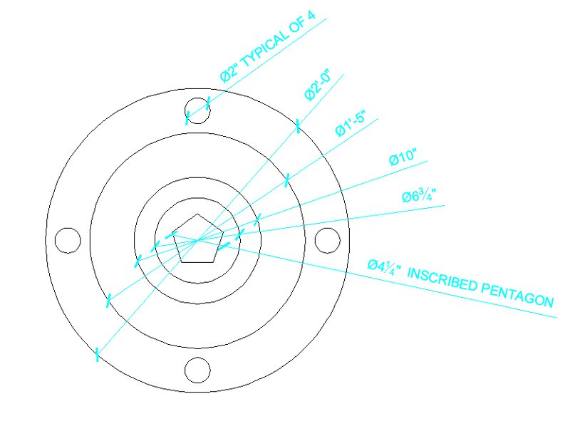
WHEEL
(click
here for link to "How To" video)
16.
How to draft the "Wheel"
IRREGULARIS
(click
here for link to "How To" video)
17.
How to draft the "Irregularis"

SAW
HORSE
(click
here for link to "How To" video)
18.
How to draft the "Saw Horse"

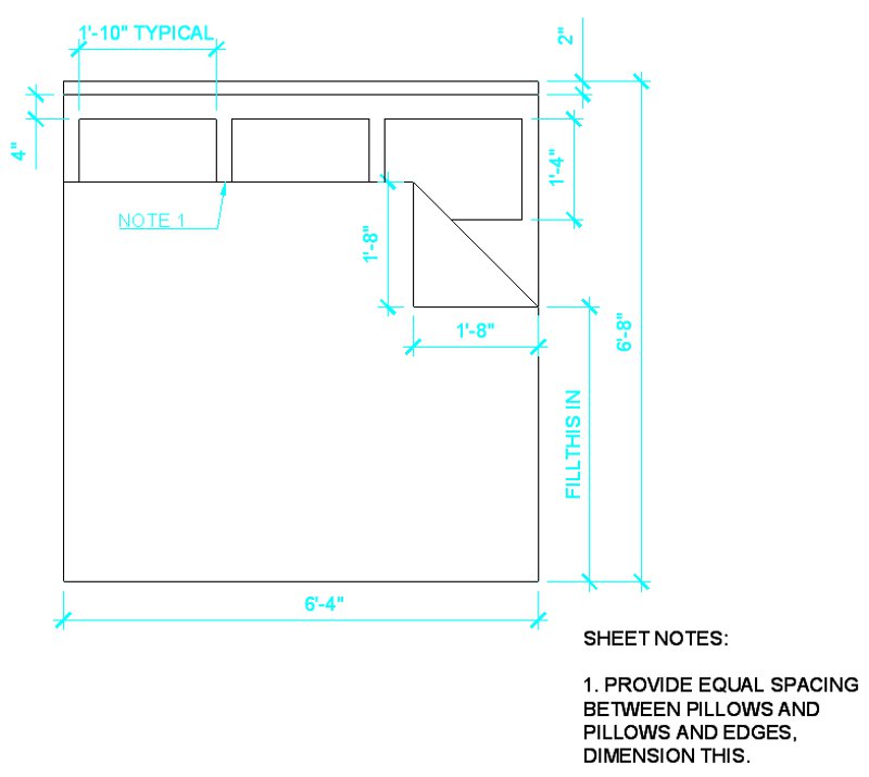
KING
BED
(click
here for link to "How To" video)
19.
How to draft the "King Bed"
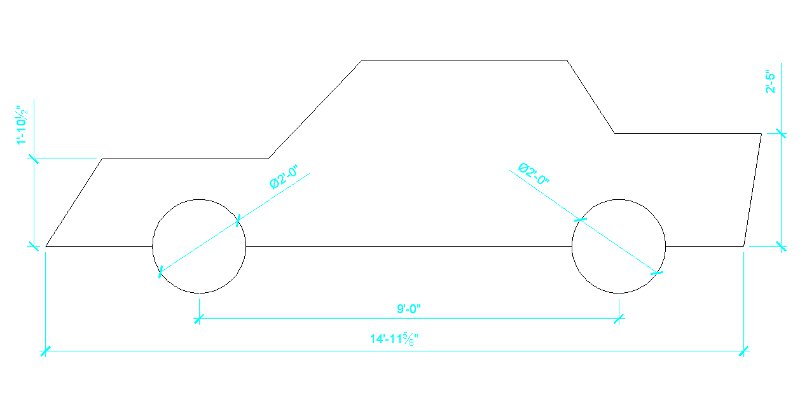
CAR
Set
up the wheels and set them apart from each other as shown. The rest
is your design, provide at least 10 dimensions.
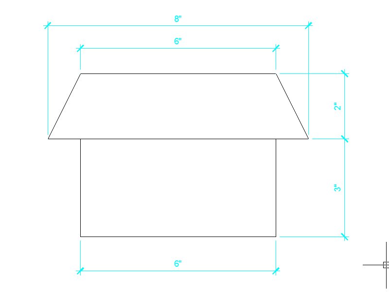
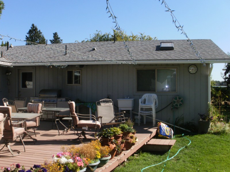
HOUSE
ELEVATION IMAGE
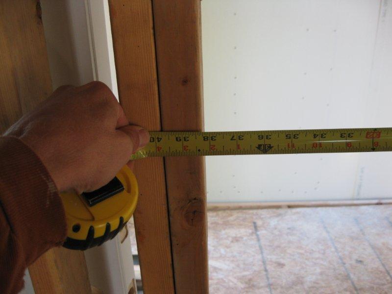
Use
an image like this or draft a likeness of your own wall from your dream
house design. You need to know some dimensions on your proposed wall
in order to draft to scale similar unmeasured objects in your drawing.
In the example below, the walls are 8' high with a roof overhang of 2'.
The back door is 80" by 31-3/4" at the opening with 2" brick mold.
The window trim is 3-1/2" and the grooves in the siding are 8" wide.
These measurements are used to draft similar unmeasured objects in the
image.
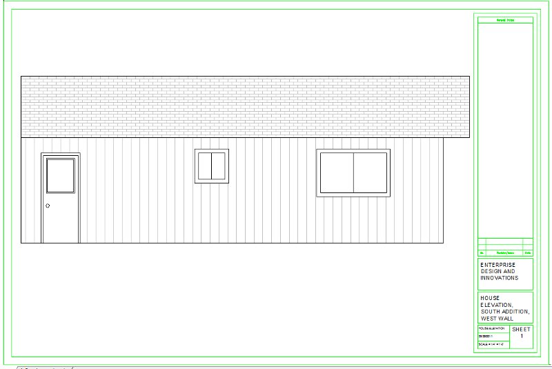
HOUSE
ELEVATION DRAWING

HOUSE
ELEVATION DRAWING WITH HATCHING
|
- |
|
|
 |
|
-
Week
3:
Design
Assignment due: For
your ICE on Tuesday you will be required to hand in 4 items:
-
Produce
the exercises from Week 2, one of these will be handed in.
-
A measured
and drafted wall elevation in AutoCAD.
-
Produce,
in class, an exercise that will be handed out.
-
Demonstrate
a proper template file
Everything
will be drafted on your new template file. |
Read
and practice ahead:
View
the Instructional Videos below showing how to set
up your template file and to draft the CMU drawing.
View
the following videos from the Autodesk website for AutoCAD 2012.
Download,
view, print (if you like) read and practice tutorials 4 and 5 from the
Autodesk website for AutoCAD 2012 (2011). Download and then unzip
the downloaded files:
In Tutorial
5 we will not be covering, in this class, the different linetypes (we will
stick with the basic solid line) and lineweights (we will stick with the
default size). |
Class
exercises and assignment details:
In Class Evaluation (4 items)
Click
here for your Week 3 ICE Grading Criteria.
You will print out and hand in the 4 items listed below stapled to your
ICE Grading Criteria. Print out your Wall Elevation exercise before
class. You will be graded on the following:
-
Produce the exercise from the
handout at the beginning of class.
-
This exercise
will be similar to the exercises from Week 2 and you will have 30 minutes
to complete it.
-
All elements
-
Lines
connect, horizontal and vertical
-
A sized
sheet, landscape orientation, appropriate scale, centered
-
Dimensions,
scaled, orderly, larger dimensions on the outside
-
Fill in
dimensions as shown
-
Title
block updates including, sheet names, date, and scale
-
Hand in one of the exercises
from Week 2 as instructed during the evaluation.
-
All elements
-
Lines connect, horizontal and
vertical
-
A sized sheet, landscape orientation,
appropriate scale, centered
-
Dimensions, scaled, orderly,
larger dimensions on the outside
-
Title block updates including,
sheet names, date, and scale
-
Hand in the Wall Elevation Assignment
per the instructions below:
-
Choose a wall and draft an elevation
of this wall using your new template file, re-save your template using
an appropriate name.
-
Any wall type, inside or out,
you may draft a wall from your sketched floor plan.
-
Measure this wall using techniques
discussed in class
-
Draft in Model Space, print
in Paper Space
-
Must contain at least 10 elements
(elements are considered some sort of enclosed geometry such as rectangles,
circles or ellipses).
-
Dimension in a manner similar
to the exercise in Week 2
-
Orderly and easy to read
-
Dimensions not covering objects
or other dimension lines (like the 2" dimension for the door trim)
-
include both horizontal and
vertical location dimensions
-
Measure from walls for horizontal
window and door locations
-
Larger dimensions on the outside,
shorter dimensions on the inside
-
Use appropriate scale so it
fits on your A sized template file in Paper Space.
-
Title block updates.
-
Demonstrate a proper template
file.
-
Title block and border lines
connect
-
Borders center on page
-
Proper line and text colors
-
Text sizes, CAPITAL lettering,
-
Orderly and aligned text
-
Centered text for company name
and project name
-
Hidden viewport when printing
Out of
class exercises:
Practice
and produce the following exercises, draft these as separate files with
the appropriate title block updates as described in class on your renamed
Template1.dwg file. At least one of these will be due at the time
of the In ICE at the beginning of class on Tuesday in Week 4.
ARCHITECTURAL
OBJECTS
Make
Blocks out of these objects and include them into your floor plan.
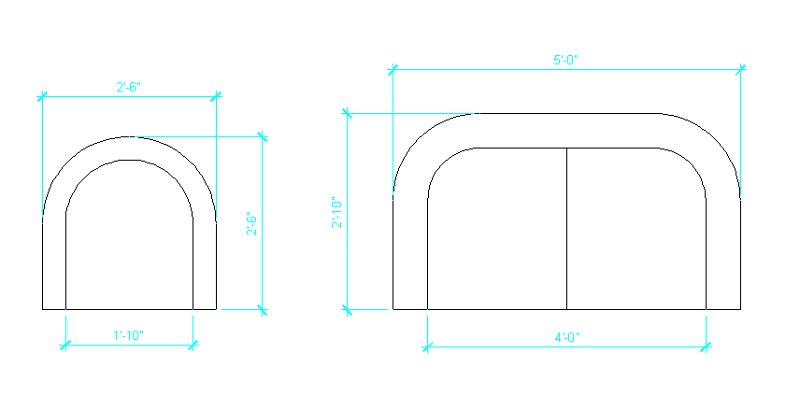
THE
COUCH
Also
create a love seat and single seat using the same design as below.
Make
Blocks out of these objects and include them into your floor plan.

STAIRS
(click
here for link to "How To" video)
20.
How to draft an elevation of a stair design

CHAIR
AND COUCH
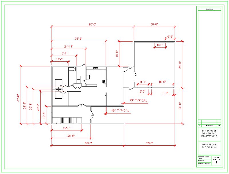
FLOOR
PLAN SAMPLE
Draft
your own floor plans, both first and second floors using your sketches
from Week 2 as guides. Following the image below are various instructional
videos showing various tips and tricks on how to put together your floor
plan. These videos cover the items that we went over in class plus
some bonus footage that will make your drawings more complete and easier
to draft.
-
Each exterior
side has to be in whole foot units (no inches or fractions).
-
Each interior
wall dimension has to be in whole foot and inch units (no fractions).
-
Call out
only once an exterior wall dimension, label this "typical" if you want
(fractions allowed).
-
Call out
only once an interior wall dimension, label this "typical" if you want
(fractions allowed).
Floor
Plan
(click
here for link to "How To" video)
21.
How to draft floor plan with techniques and tips
Instructional
Videos:
View
the instructional videos at this link AutoCAD
3 Construction Drafting regarding the subjects listed below:
33.
& 34. Using the Design Center and to how to insert and modify the Dynamic
Block Door
|
- |
|
|
 |
|
-
Week
4:
Design
Assignment due: For
your ICE (In Class Evaluation) on Tuesday you will be required to hand
in 5 items:
-
Produce
the exercises from Week 3, one of these will be handed in.
-
Draft, in
AutoCAD, your floor plans (2 total) of your dream house that you hand sketched
from Week 2, hand in the hand sketched floor plans also.
-
Produce,
in class, a floor plan exercise that will be handed out like last week.
|
Read
and practice ahead:
Your
Revit textbook, chapters 1 through 4. Instructional
Videos below. Read and practice these before class on Tuesday. |
Class
exercises and assignment details:
In Class Evaluation (5 items)
Click
here for your Week 4 ICE Grading Criteria.
You
will print out and hand in the 5 items listed below stapled to your ICE
Grading Criteria. Print out your Floor Plans before class.
You will be graded on the following:
-
Produce the exercise from the
hand out at the beginning of class. This will be a small floor plan
of an apartment, you will have 30 minutes to complete
it.
-
Hand in one of the exercises
from Week 3 as instructed during the evaluation.
-
Hand in your Dream House Floor
Plan Assignment per the instructions below. 2 sheets plus your hand
sketched floor plans from Weeks 1 and 2 (3 items total) (40 points total
(20 points per sheet)):
-
Using your sketched drawing
as a reference from Weeks 1 and 2 draft both your first and second floor
plans, both the hand sketched and CAD plans must be similar.
-
One floor per sheet, 2 sheets
total.
-
Sheets are aligned from 1st
floor to 2nd floor
-
Must contain the rooms and elements
from your sketched floor plan although some minor variations are permitted
-
At least 8 rooms per floor
-
3 bedrooms at least
-
Front and back doors at least
-
Garage with doors openings
-
Stairs similar to the example
in Week 3, provide a landing on the top and bottom
-
Insert blocks
-
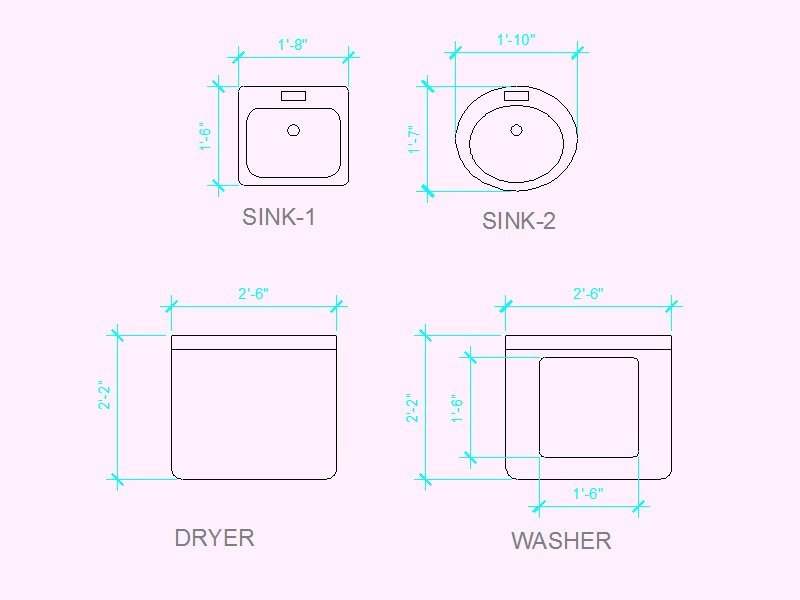
7 blocks made in Weeks 2 and
3: the king bed, the 2 sinks, washer, dryer and the couches (3)
-
Various blocks from the Design
Center drawing, including the dynamic block for the doors, 10 minimum,
repeated items counted once.
-
Dynamic block door must have
the wall thickness settings changed (refer to the videos).
-
Windows per the videos.
-
Dimension interior and exterior
wall locations only, in a manner similar to the floor plan example in the
Week 3 section above (refer to the videos).
-
Overall house dimensions
-
Whole foot units, no inches
or fractions
-
Orderly and easy to read, not
covering objects or other dimension lines
-
Longer dimensions on the outside,
shorter dimensions on the inside
-
Dimensions for the interior
walls from a common exterior outside wall edge as shown.
-
Be consistent regarding which
interior wall edge used, either the 1st or 2nd wall
-
Whole foot and inch units (no
fractions (exceptions for the stairs and instances involving wall thickness
issues)).
-
Longer dimensions on the outside,
shorter dimensions on the inside
-
Dimension once each of the 2
wall thicknesses, interior and exterior (similar to the example in the
Week 3 section above)
-
Appropriate dimension scaling
-
Room labels for each room
-
Use appropriate sheet scale
in the viewport so it fits on your A sized template file in Paper Space.
-
Appropriate title block updates,
center your drawing
-
Extra credit for extra details
(extra rooms, counter tops, extra blocks, landscaping, etc...)
Out of
class exercises:
Download,
from the publishers of the Revit textbook, various files related to the
book. For Thursday's class download a file in the Chapter 2 Resource
File section by clicking on the HTTP link and downloading the "029961c02_dataset.zip"
file. Once downloaded, unzip this file into a folder on your flash
drive or network save location. From this folder open the file named
"Dataset_02_03.rvt" . This Revit file is the model that you see on
the cover of the book and is referenced various times throughout the book.
We will be taking a tour of this model in class on Thursday.
Start
on your Dream House floor plan using Revit by laying out the walls from
your AutoCAD floor plan or your hand sketched plan. A portion of
your Revit floor plan will evaluated next Tuesday for your ICE.
-
Before you start your Dream
House design, like you did in Week 2, spend some
quality time looking at and studying homes and home designs
and consider what features you both like and dislike about them both inside
and out. Review the guidelines from Week 2.
Follow
the steps for Defining Wall Structure starting on page 104
in your textbook. An exercise like this will be part of Week 5's
ICE. More information to follow, check back.
Instructional
Videos:
View
this week's Instructional Videos at this link Revit
1 Getting Started regarding the subjects listed below:
1.
Revit Architecture Week 4, Getting Started with a Revit Model
2.
Modeling an Apartment, Part 1, Copying Walls
3.
Modeling an Apartment, Part 2, Laying out and Dimensioning Exterior Walls
4.
Modeling an Apartment, Part 3, More on Laying out Dimensioning Exterior
Walls
5.
Modeling an Apartment, Part 4, Laying out and Dimensioning your Interior
Walls
6.
Modeling an Apartment, Part 5, more Laying out and Dimensioning Interior
Walls
7.
Modeling an Apartment, Part 6, Interior Walls Plus Trim Tools
8.
Modeling an Apartment, Part 7, Laying out a Floor, Editing & Viewing
Functions
9.
Modeling an Apartment, Part 8, Installing Doors and Components & Camera
View
10.
through 14. Create a Roof in Revit
15.
through 18. Define a Wall Structure or how to Modify a Wall
Instructional
Images:
Information on some basic
residential building design elements are shown in the images below.
The images for this week show various elements that go into a simple foundation
and first floor wall construction.
The image below shows the
site work prior to the setting up of the forms for a concrete foundation
footing and stem wall. These foundation elements will be attached
to the existing house providing a bedroom addition.
The forms as they were being
set up for the concrete. This will be a "monolithic pour" pouring
concrete for both the footing and stem wall at the same time.
The completed forms on the
front of the house as the concrete was being poured.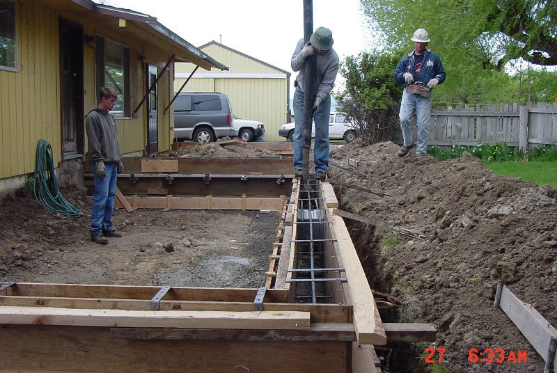
The new footing and stem
wall foundation. Notice the embedded anchor bolts sticking out. 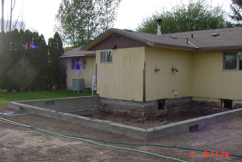
Two days later, the new structural-floor
is constructed on top of the new stem wall foundation. On top of
the stem wall is a 2x6 treated sill plate, bolted down with the embedded
anchor bolts. The sill plate serves as a interface between the wooden
sections of the exterior wall and the concrete foundation. The sill
plate, without treatment, would be subjected to decomposition over time.
The joist hangers attach to this sill plate and joists attach to the inside
of the hangers. The joists serve as horizontal structure for the
structural-floor. 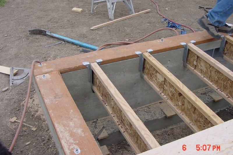
The structural-floor made
of 7 layered plywood at 1-1/4" thick is glued and nailed to the joists.
The sill plate and floor are coplanar to the exterior surface of the stem
wall. The plywood has holes cut into it to accommodate the nuts,
washers and anchor bolts on the sill plate. 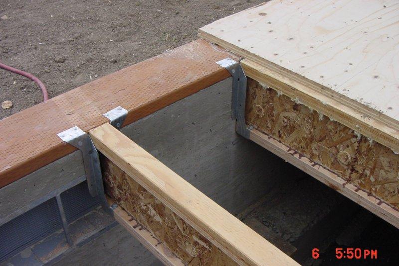
The image below shows the
completed structural-floor and is ready for the exterior walls. It
is the top surface of the structural-floor that serves as the first floor
plane. When modeling, the first floor is extruded below this plane
and the first floor walls are extruded above it.
A close-up of the previous
image where the new addition meets the existing house and shows how it
is constructed. Notice how the sheathing and siding cover the edge
of the structural-floor and extends about 2 inches below the top of the
stem wall foundation. This allows water to shed off the siding and
onto the ground (and not into the house). When modeling walls the
"Core Face: Exterior" plane is coplanar to the stem wall, sill plate and
edge of the structural-floor. The "Finish Face: Exterior" plane is
the furthest extend of the wall and includes the 1/2" sheathing (1/2" plywood
or OSB) and 5/8" T-111 siding. 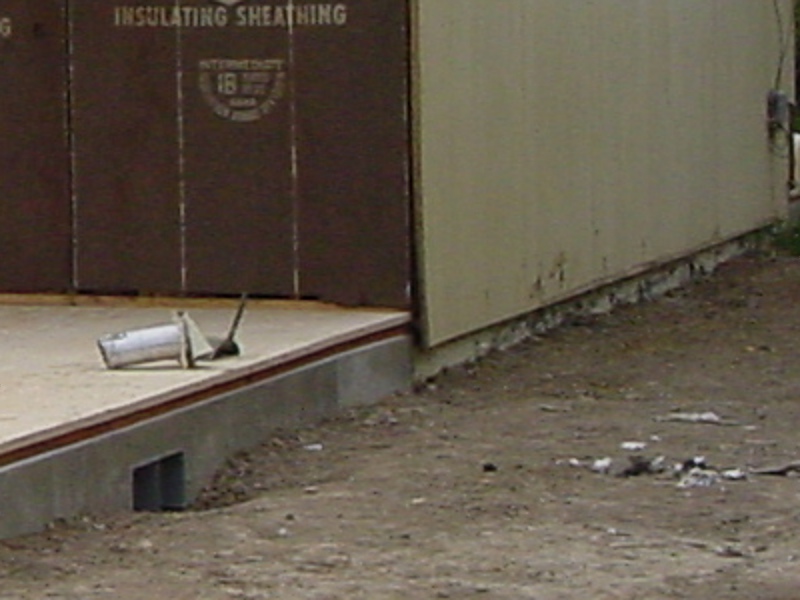
An image of the completed
floor from the crawl space below and includes insulation and ductwork.
This image faces the stem wall shown in the image above. 
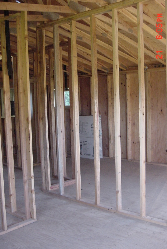
The interior of this space
after interior walls, roof and some plumbing have been installed, facing
the same direction as the image above. It shows interior walls (2x4
construction, 3-1/2" wide) and exterior walls with sheathing (2x6 construction,
5-1/2" wide). The sheathing (1/2" plywood or OSB) is on the outside
of the "Core Face: Exterior" plane and before the "Finish Face: Exterior"
plane so it is on the outside of the core and exterior of the structural-floor,
sill plate and stem wall plane. To finish the exterior of the exterior
walls you would add a layer for the dimensionless wind barrier on the outside
of the sheathing and then siding. On the inside of the core you would
add the structure (2x6 5-1/2" wide). On the interior of the exterior
wall you would add a finish element 1/2" drywall. Occupying the same
space as the structure of the wall (the 2x6) would be the insulation.
The interior wall sandwich would be 1/2" drywall on either side of the
core structure (2x4, 3-1/2" wide) making the wall 4-1/2" thick.
Regarding the creation of
Revit Families:
The images below display
some of the dimensions associated with the construction of doors and windows.
We will not be covering the construction of Revit families but if you want
to pursue it on your own you may find the information and images below
useful. If you want to explore Chapter 17 you can use the information
below to help modify the existing families provided by Revit or to create
new ones.
The immediate images that
follow show dimensions associated with a standard 36" door installation.
The image below is a 36" exterior door (6-1/2" exterior wall thickness).

The actual door size is 35-7/8".

The actual door size is 35-7/8"
(close up).
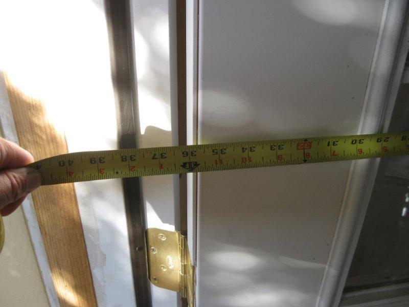
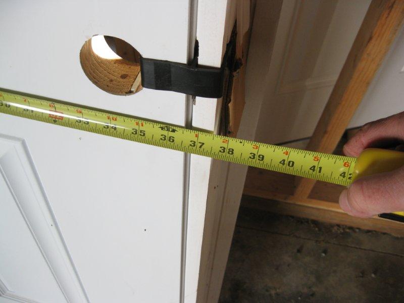
The exterior dimension size
is 40" including the exterior trim (brick mold).
The actual opening of the
door, inside clearance is 36". This measurement determines the door
size.
The actual opening of the
door, inside clearance is 36" (close up).

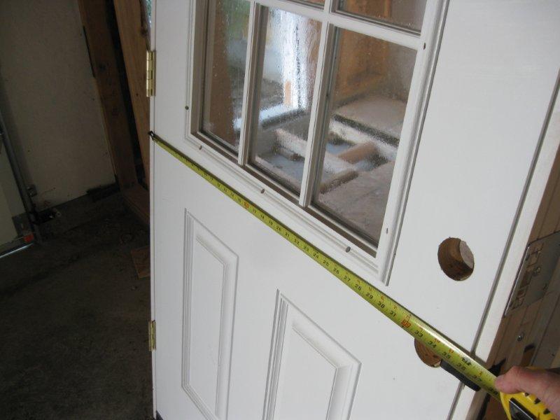
The door frame on the interior
of this door is 37-1/2".

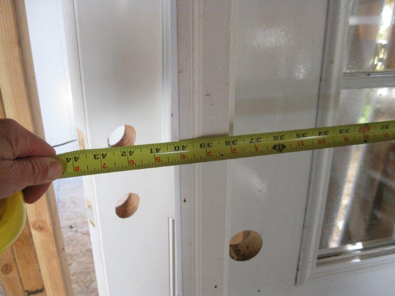
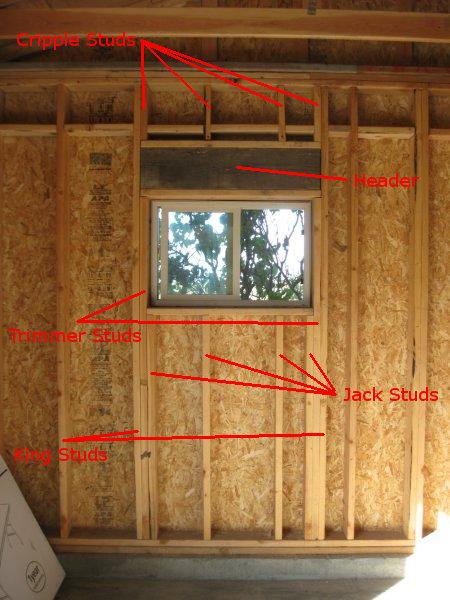
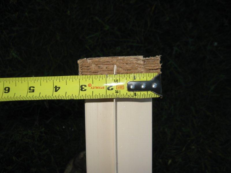
The images that follow show
dimensions associated with a standard 3' x 2' window installation. The
image below shows a framed window opening and window on the interior of
a garage for 3' x 2' window.
The framed window opening
(rough opening) for 3' x 2' window (close up). This is one of the
measurements that determine the window size.

The framed window opening
(rough opening) for 3' x 2' window (close up). This is one of the
measurements that determine the window size.

An uninstalled 3' x 2' window.
The window measures about a 1/2" less on each side referencing the window
size. This gives us about a quarter inch on all sides of the
window for adjustments, using shims, during installation.

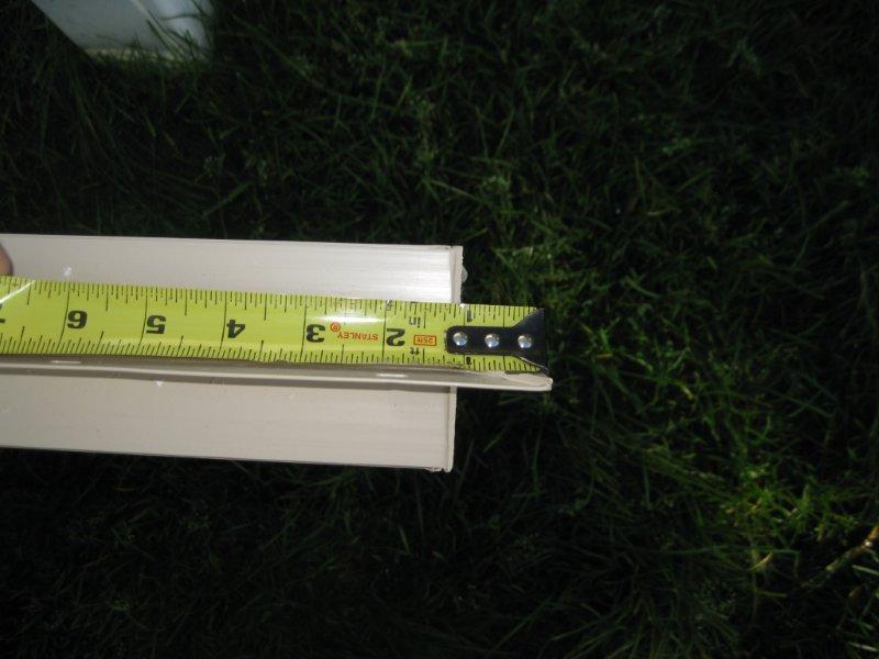
Window and frame is about
3" thick.
The nailing flange is positioned
about 1" back from the exterior edge of the window.

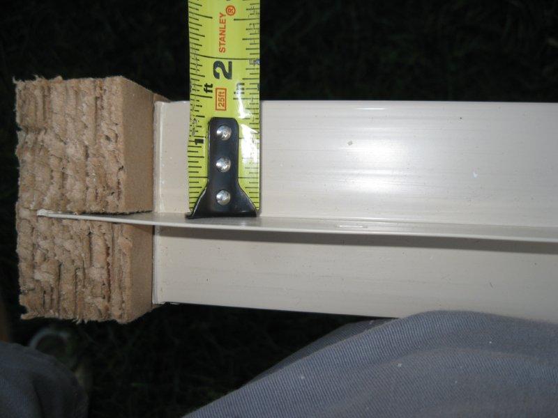
The nailing flange is about
1" long.
A finished window from the
exterior excluding caulking and paint, notice the nailing flange is covered
by the window trim.
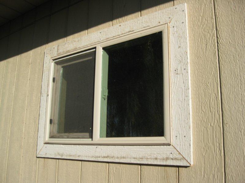
A finished window on the
interior with a window sill. Revit will have library windows with
the trim and window sills included.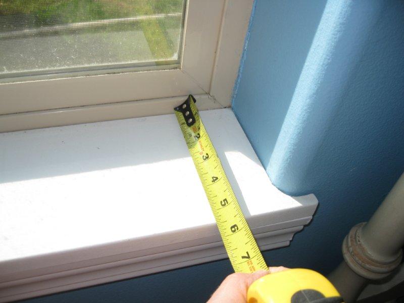
The door frame on the interior
of this door is 37-1/2" (close up). Allow for about 38" rough door
width opening. Revit will cut this out for you.
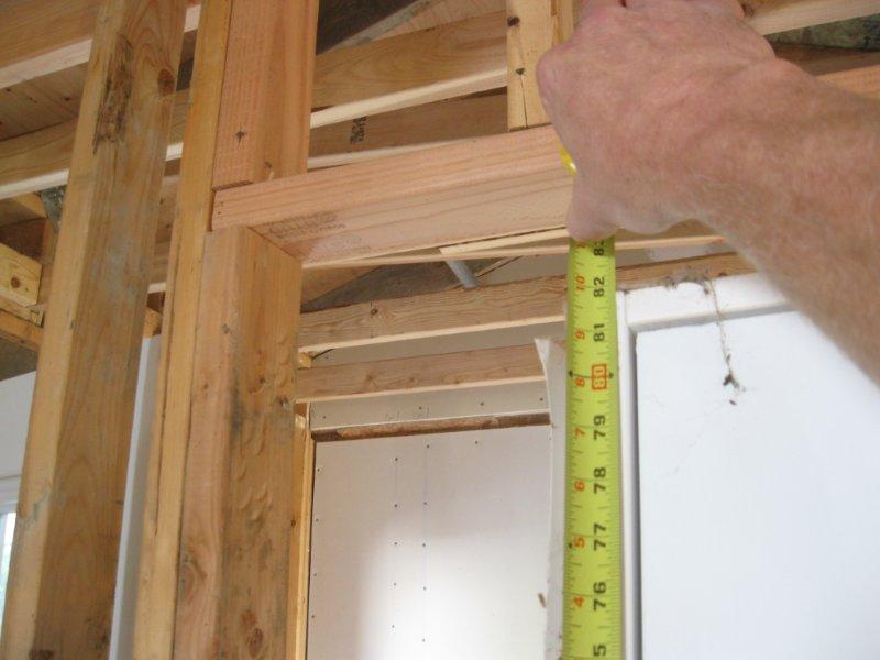
The framed door opening.
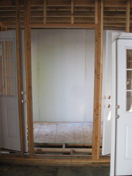
The framed door opening (rough
opening) height (about 81-3/4"). Allow for about 82" rough door height
opening. Revit will cut this out for you.
The framed door opening (rough
opening) width.

The framed door opening (rough
opening) width at 38-1/4" (close up) (usually 38"). This gives us
about a 3/8" on each side of the door for adjustments, using shims, during
installation.
-
|
- |
|
|
 |
|
-
Week
5:
Design
Assignment due: For
your ICE on Tuesday you will be required to transfer to me 4 assignments
in 2 files:
-
Your Dream
House model produced and designed in Revit.
-
Produce
the 3 wall types (named as Defining Wall Structure in the text book),
one as described in the textbook, one as demonstrated in class and the
video in the Week 4 section above and the third a custom wall of your choosing
(refer to the wall videos above). These walls will be included in
your Dream House model.
-
Produce,
in class, a simple Revit model of a simple home.
|
Read
and practice ahead:
Your
Revit textbook, chapters 4 and 5. Read and practice these before
class on Thursday. |
Class
exercises and assignment details:
In Class Evaluation (2 items)
Click
here for your Week 5 ICE Grading Criteria.
You
will produce and transfer to me, at the instructor's computer, the 2 items
listed below, consisting of 4 assignments, and hand in your signed and
dated ICE Grading Criteria.
-
Produce the exercise from the
hand out at the beginning of class. This will be a simple apartment
design similar to last week's ICE. You will
have about 45 minutes to complete it. You will be graded in a similar
manner as described for your Dream House evaluation below.
-
Hand in your Dream House model
file, you will be graded in 3 parts, the first on your custom wall, the
second on Defining Wall Structure and
the third on the progress on your Dream House design
-
Produce
the 3 wall types (named as Defining Wall Structure in the text book),
one as described in the textbook and the two others as demonstrated in
the video in the Week 4 section above.
-
The requirements
for your custom wall are iterated in the videos in the Week 4 section above
-
Name these
as described in the book and in class
-
Place these 3 walls in front
of the north elevation symbol on the north side of your home, parallel
to the north wall on your house.
-
Make each wall 16 feet long
and 6' 6" apart from each other and place permanent dimensions on them.
-
"Align" the edges of the walls
to each other and lock this constraint.
(You will know that you have
done the above steps correctly if all three walls move as one unit without
any walls being left behind, stretching or the dimensions changing.)
-
Your Dream House design in Revit
with the following elements:
-
3 levels, named (in CAPITALS)
something similar to (depending on your design) FIRST FLOOR, SECOND FLOOR
and ROOF
-
Level line and target are aligned
together and separated by whole or half foot increments
-
Exterior walls
-
Connected and oriented properly
-
From the FIRST FLOOR to the
ROOF level
-
Permanent dimensions in whole
or half foot increments
-
FIRST FLOOR Interior walls
-
Connected, extended and trimmed
-
From the FIRST FLOOR level to
the SECOND FLOOR level
-
Permanent dimensions in whole
foot and inch increments
-
Front door and windows of your
choice, 2 different window types with a total of 10 elements (read and
practice from the book for this function).
-
First floor, a modified 6" concrete
slab and the second floor of your choice (read and practice from the book
for this function)
-
Add "Components" like beds and
appliances to help size your rooms and for extra credit.
Instructional
Videos:
Below
is a link to a video showing a time lapse construction of a dream home.
It demonstrates the use of construction materials, elements of various
construction components such as walls, floors and roofs. This link
will take you to YouTube where you can find similar videos: Weaver
Homes time lapse
View
this week's Instructional Videos at this link Revit
2, Basements and Such and Revit
3, Stairs and Curtain Walls regarding the subjects listed below:
19.
through 28. Modeling a Basement with a Site Toposurface and Building Pad
29.
Creating a Room Label
30.
Modifying a Floor to Add a Ceiling
31.
Adding Door Like Room Openings
32.
Installing a Front Door with Sidelights and Equality Dimension Constraints
33.
Adding Spiral Stairs
34.
through 37. Adding Linear Stairs, Floor Cuts and Railings
38.
through 43. Storefront Curtain Walls with Modifications
|
- |
|
|
 |
|
-
Week
6:
| Design
Assignment due: None
this week, your first midterm exam will be on Tuesday. |
Read
and practice ahead:
Your
Revit textbook, Chapters 6, 7 and 11. Chapter 11 is on rendering
(image generation). Read and practice these before class on Thursday.
We will
cover each of your Dream House projects individually on Thursday.
This will be the last opportunity before the Dream House presentations
on the Thursday of Week 7.
|
Class
exercises and assignment details:
Your
first examination will be on Tuesday. To prepare for the written
portion of the exam you need to be certain that you have read and practiced
all of your reading assignments, Instructional Videos and have studied
your notes taken in class.
For
the design portion of the exam you will be modeling a 3 story residence
in Revit. The residence model will incorporate many of the design
elements that have been demonstrated in class and in Instructional Videos
and include the elements listed below. You may create a template
file of these elements below and use it for the exam. You have the
time, so carefully plan out your design:
Model
a skinny rectangular shaped residential home, of your design, using the
following guidelines:
-
Scale,
make each view scaled at 1/8=1-0 if it is not already set at that.
-
Levels,
Create and or rename 4 levels: BASEMENT, FIRST FLOOR, SECOND FLOOR, ROOF.
-
BASEMENT
-9 4, FIRST FLOOR 0 0, SECOND FLOOR, ROOF
-
Create
a floor plan for the BASEMENT and ROOF levels
-
Site,
basement slab and walls as a class exercise, east-west walls at 60 some
feet, north south walls at about 20 feet, orient the house so a short end
is north (top)
-
Exterior
Walls (use your custom wall from Week 4) from the FIRST FLOOR level to
the ROOF level
-
Location
Line on the Core Face Exterior
-
The front
door is on the east or west wall, back door location of your choice.
-
Permanent
dimensions for the wall lengths, exterior edge to exterior edge.
-
Interior
Walls, Interior walls shall be Interior - 4-1/2" DW-WoodStud-DW created
in Week 4
-
Permanent
dimensions in whole foot or inch increments from common exterior wall edge
to centerline of interior wall, first floor only, no need to dimension
closet walls, no dimensions necessary on the second floor.
-
Create
and label in CAPITALS the following rooms on the first floor: Living Room,
Bedroom 1, Bedroom 2, Office, Laundry Room, Utility Room (see the video
in the Week 5 section above)
-
Create
and label in CAPITALS the following rooms on the second floor: Kitchen,
Dining Room, Living Room, Master Bed, Master Bath, Bathroom
-
Floors,
both floors: Wood Joist 10 (custom covering of your choice) - DW (drywall
on the second floor is the ceiling for the first floor, 5/8 (see the video
in the Week 5 section above)), properly name this type, span direction
oriented east and west.
-
Stairs,
style and location your choice, at least 48 wide, must have a mid-span
landing unless spiral stairs, cutout the second floor (see the videos in
the Week 5 section above).
-
Doors,
Insert the following doors, no tags:
-
Front
Door, make a cutout on the exterior wall for the door, Double Glass door
of your choice, 72 x 84, Permanent Dimensions with Equality Constraints
from the exterior walls, opens in, Sidelights (a Window in the door family)
on either side of the door at the appropriate height (see the video in
the Week 5 section above)
-
Back door
Single-Decorative 36 x 84, Permanent Dimensions in whole foot and inch
units
-
Interior
doors Single Flush 28 x 80, opens into rooms, swings to adjacent interior
wall, no dimensions.
-
Opening
Cased or Opening Elliptical as a Component for some room access in lieu
of doors (see the video in the Week 5 section above).
-
Windows,
Insert the following: each room gets at least one window, corner rooms
get at least 2 windows except for bathrooms which get only one window,
make the distribution of windows on your house symmetric and attractive,
no tags, no dimensions
-
Choose
from 3 different families, with trim (not the default fixed window), consistent
head height for each window type (not the default settings) on each floor,
excepting the bathroom windows
-
Bathroom
window Slider with Trim 36 x 24, sill height at 5 0
-
Roof,
Main roof 5/12 roof, 20 inch overhang, type is Basic Roof Wood
Rafter 8 Asphalt Shingle Insulated, make at least one of the north or
south walls of the house a gabled end, Attach Top/Base on this end (see
the video in the Week 5 section above).
-
Extra
Roofs, Insert an extruded sketched roof, shape of your choice, same type
as above, in front of both exterior doors
-
Curtain
wall, whole foot units, location and height of your choice, base offset
at least 6, mullions at a distance other than the default settings for
spacing, OK to span the first and second floors (see the video in the Week
5 section above)
-
Create
2 building sections, one north south orientation, one east west orientation,
create a 3D view, Create at least one camera view of significance and rename
this view in CAPITALS with the room name in it.
-
Components,
furniture, appliances, fixtures, etc
at least 20 non unique.
General
Notes:
-
Fix all
errors
-
No tags
except for room tags
-
Design
integrity (examples, the stairs should not have a ceiling reveal in a critical
room, windows should not cut into floors and ceilings, etc
)
-
Extra
credit for fixtures, furniture, closets and closet doors, etc
-
Extra
credit for a good layout and design (considering traffic flow, room sizes
and locations etc
)
-
Extra
credit of extra items and details beyond what is required as described
above
Instructional
Videos:
View
this week's Instructional Videos at this link Revit
4, Walk Throughs and Columns and Revit
5, Cameras and Rendering regarding the subjects listed below:
44.
through 49. Creating and Modifying a Revit "Walk Through"
50.
through 53. Inserting Architectural Columns
54.
through 64. Camera Views and Image Rendering
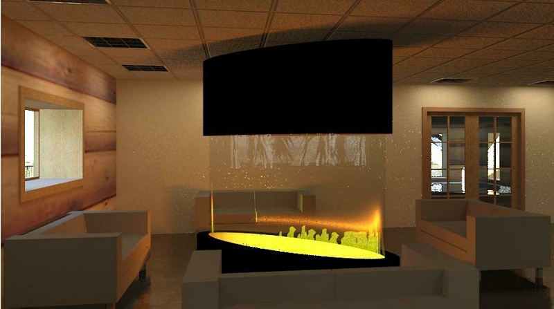
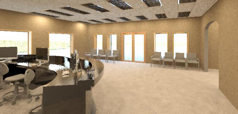
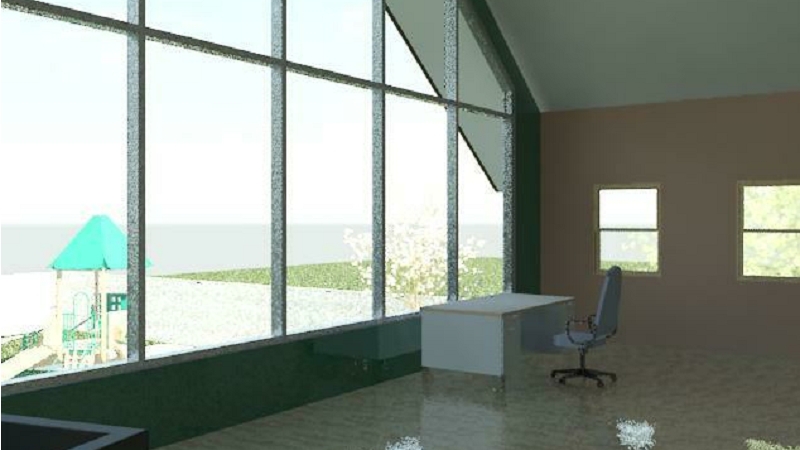
Another way Revit Architecture
allows you to visualize your project is through image renderings of certain
Camera views in your project. View and practice the videos below.
Some image Renderings will be a requirement for your Dream House presentations.
|
- |
|
|
 |
|
-
Week
7:
| Design
Assignment due: Dream House project presentation
and model. Commercial Project proposal. You will be evaluated
on 4 items this week. |
Read
and practice ahead:
Your
Revit textbook, Chapters 13 and 14. Read and practice these before
class on Thursday. |
Class
work and assignment details: Click here for
your Week 7 ICE Grading Criteria, available before class on Thursday.
You will be evaluated on 4 items this week:
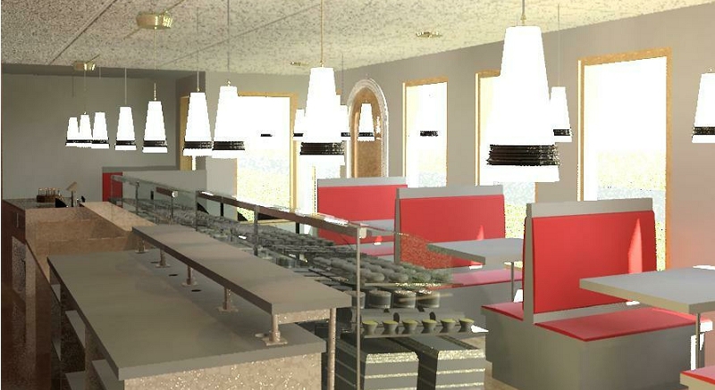
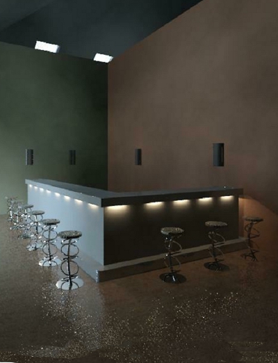
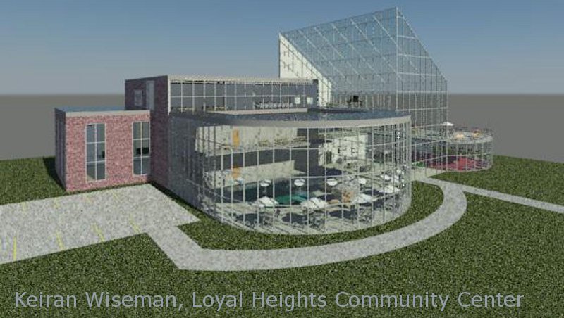
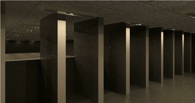
Commercial Project Proposal,
20
points total Back
to Index
Send to me by Tuesday, via
email, your proposal for your Commercial Project. This is worth 20
points out of the 200 points available for your Final Commercial Project
(10% of your grade). Write a single paragraph describing the items
listed below.
-
Type of project
-
Examples include: restaurants,
schools, auto show rooms, hotels, theaters, malls, grocery stores, coffee
shops, office buildings, restaurants, factories etc... essentially any
building engaged in commerce that may be open to the public, see the last
few class websites to get some additional ideas.
-
Describe the project, traffic
flow, customer areas, production areas, offices
-
How large do you anticipate
the project to be (described as rooms, floors, square feet, etc...)
-
What sort of components or features
do you anticipate placing in your project.
Dream House Presentation,
Peer Evaluation, 20 points total
Back to Index
The following link shows
the evaluation form that will be given to you in a book form at the beginning
of class on Thursday. You will be evaluating other students' projects
and be evaluated on the listed criteria except for the item on the toolbar.
The student(s) that receives the best overall evaluation from your peers
will have your model printed out on our 3D printer. It will be about
3 to 6 inches longs at about a 1:500 scale (with a removable roof!).
Dream House Presentation,
My Evaluation, 10 points total
Back to Index
The following is a guide
that I will evaluate you on and may help you when you organize and practice
your presentation:
-
Introduction, provide your name,
major and class position (senior, junior, etc...)
-
Introduction to your project,
type of house, location, what it will be built out of
-
Tour, 3D view around the house,
entry into the house, show floor plans and traffic flow from front door
or entry or stairs, talk about the rooms
-
Move on through the model and
demonstrate any features that you think are significant in your home using
the usual views (plans, elevations, sections) plus:
-
Camera views of something significant
(8 minimum)
-
Adjust view depth, range and
settings to get a decent view
-
Image renderings of the inside
and outside of the house (4 minimum)
-
Adjust view depth, range and
settings to get a decent image
-
Walk Through video (1 minute)
-
Adjust view range, height and
settings to get a decent video
-
Presentation at 5 to 6 minutes
in length
Dream House Model Evaluation,
40
points total Back
to Index
The following is a check
list that I will use to evaluate your Dream House model, hand in this electronic
file at the instructor's computer during your presentation. Some
items have not been covered in class so look these up in your book or online
resources.
-
Site Plan toposurface surface,
contours, building pad, subregion, property line (within the contours and
enclosed geometry), contour elevation labels, landscaping
-
Various levels (at least 3),
named (in CAPITALS)
-
Level line and target are aligned
together, whole or half foot increments
-
Floor plans are for each level
-
Exterior walls, custom wall,
connected and oriented properly, from your first floor to your roof level
-
Permanent dimensions, whole
or half foot increments, base line from exterior wall edges to each exterior
wall edge
-
First floor Interior walls,
custom, connected from your first floor level to your second floor level,
connected to bottom of floor above (second floor walls in a similar manner)
-
Permanent dimensions in whole
foot or inch increments, from the exterior wall edge, to a consistent element
of the interior walls
-
Room labels with consecutive
numbers CAPITALS
-
Floors, custom coverings (carpet,
vinyl, wood), at least 3, cut out exterior walls
-
Ceilings of your choice, if
not part of the floor above
-
Front door, Interior doors of
your choice, less than 36" wide, opens correctly
-
Windows, 3 different window
types, one window per room per wall, consistent head height
-
Stairs, at least 1 set, greater
than 36 wide, no errors, cut out floor above
-
Roof, custom, Foot Print, overhang,
Roof by Extrusion (like over a door)
-
Components like furniture, fixtures,
equipment to fill the house, complete each room
-
Extras for extra details and
features beyond what is listed above, extras must fit the model and enhance
the design.
General Notes:
-
Fix all errors (1 point each)
-
No tags except for room tags
(1 point each)
|
- |
|
|
 |
|
-
Week
8:
Design
Assignment due:
For your ICE (In Class Evaluation) on Tuesday you will be required to complete
2 items:
-
An external
video of your Walk Through of your Dream House model.
-
Progress
on your Commercial Project with elements added during the evaluation
|
Read
and practice ahead:
Your
Revit textbook, Chapters 14, 15 and 16. Read and practice these before
class on Tuesday. |
Class
exercises and assignment details:
In Class Evaluation (2 items)
Click
here for your Week 8 ICE grading criteria. You
will create, from your existing embedded Walk Through video, an avi file
of your Dream House to be handed in at the instructor's computer.
Show progress on your Commercial Project. Hand in these 2 items in
one folder with your name in it at the instructor's computer. Print
out, sign and hand in your ICE Grading Criteria.
-
A video
of your Walk Through of your Dream House model.
-
Export
the video external to the model, *.avi format, "Cinepak codec by Radius"
for the format, keep it about a minute in length.
-
Realistic
view, decent perspective (not narrow or too wide)
-
800 pixels
wide
-
Inclusive
(various rooms) and complete (show most of the rooms on a floor)
-
Path from
the outside through the inside and back out again
-
A slower
pace than the default settings, a walking pace
-
Don't
go through walls
-
Extra
credit for going up or down floors and having the camera look up, down
and around like the Instructional Videos demonstrate
-
This may
take a while so plan on working on other homework while it is compiling
-
Progress on your Commercial
Project.
-
Show at least exterior walls
and and custom levels
-
Provide elements that give a
general impression of the size and shape of your project such as external
and internal walls or a site plan.
-
Elements added during the evaluation
Out of
class exercises:
Create
a customized titleblock template including a logo, this exercise will be
evaluated in Week 9
-
Modify
an existing titleblock template file downloaded from the Sybex website
as demonstrated in the videos below.
-
Download
and resave the "Titleblock SP.rfa" file and rename it to a name of your
choosing in a folder of your choosing (perhaps something similar to "Titleblock-Jones-Construction.rfa").
-
Make modifications
as demonstrated in the videos below
-
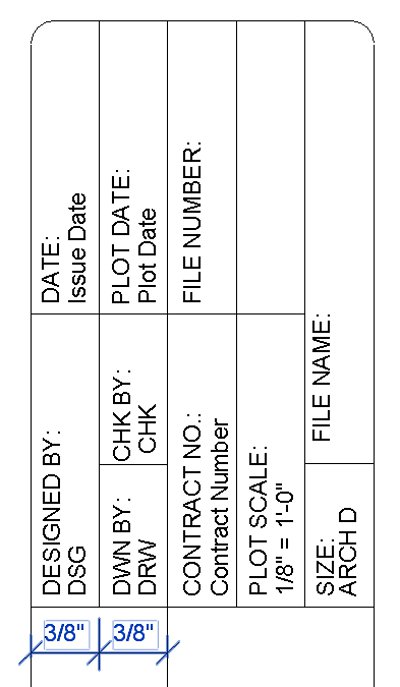
Also make
modifications to the portion of the title block shown below.
-
The lettering
in this portion of the Titleblock are both Text and Labels
both at 3/32".
-
Dimensions
shown are for your reference and are the spacing between the lines shown.
Provide this spacing but do not include these dimensions on your Titleblock.
-
Design
a logo for your titleblock in a style of your choosing as instructed in
the videos below.
-
Include a company name, address,
phone number and website address below, nearby or included in your logo.
-
Choose a name and style that
fits your career ambitions or personality. You may design something
in Revit, AutoCAD or another image program. Use the following criteria:
-
Your logo must be unique
-
An image or AutoCAD file
-
Inserted where the Revit logo
is on the titleblock template
-
stretch out the space on the
titleblock for your logo if necessary (make it fit the space and look neat)
-
Does not have to look 3D or
in color (they usually are not in color on construction drawings)
-
Include some graphical styling
including various line sizes, fonts, hatching and other techniques
-
extra credit for extra design
styling
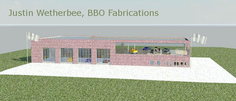
Below
is my logo and would represent a design that meets the criteria described
above.

Also consider some
designs that can be found on the web. Below are some images of some
AutoCAD files of logos from some companies that I have worked with in the
past. The logos had been produced in AutoCAD and print in black,
white and gray shading. The colors drive line thicknesses or gray
shading. These logos are included on construction drawings.

Instructional
Videos:
View
this week's Instructional Videos at this link Revit
6, Sheet Template and Curtain Wall Door regarding the subjects listed
below:
65.
through 75. Setting up a Sheet and Titleblock Template File
76.
Inserting a Curtain Wall Door
-
|
- |
|
|
 |
|
-
Week
9:
Design
Assignment due: For
your ICE (In Class Evaluation) on Tuesday you will be required to complete
3 items:
-
Download
the Revit model at the link as instructed in class and incorporate the
various items listed below
-
Progress
on your Commercial Project including sheet items with a modified Titleblock
with logo
-
Print out
your first floor plan of your project
Changes
have been made to the check list below excluding the the requirements for
making schedules (room, furniture and door). We have not covered
those items yet but they will be part of next week's evaluation.
The items modified have a line through the text (strikethrough). |
Read
and practice ahead:
Your
Revit textbook, Chapters 11 and maybe 18. Read and practice these
before class on Thursday. |
Class
exercises and assignment details: More details later.
In Class Evaluation (3 items)
Click
here for your Week 9 ICE grading criteria and for
a drawing of the project click here.
Download
and complete the Revit model at the link given in class. Show progress
on your Commercial Project per the guidance below including your sheet
family embedded in your Commercial Project. Print out a half sized
sheet of your first floor plan of your project on the 6015 printer.
You will have 1 hour to complete these items. At the end of the evaluation,
hand in the printed drawing and the ICE Grading Criteria along with both
computers files in the appropriate folder at the instructor's computer.
Download
the Revit model at the link given in class and incorporate the following
items as demonstrated in Instructional Videos in class or as read and understood
from the textbook. You will have 60 minutes to complete these items.
Complete the Revit model
incorporating the following items:
-
Dimensions as shown, interior
walls to the wall center
-
Fix the flashing floor
-
Create a ceiling, 2' x 4' ACT
System, offset from the GROUND level by an amount, align the ceiling grids
and dimension as shown
-
Install Troffer lights and suspended
lights as shown, line these up and insert dimensions as shown
-
Modify the curtain grids and
delete the mullions on the curtain wall as shown
-
Install a curtain wall door
as shown
-
Insert Rooms with room separations
and Room Tags as shown
-
Include the following rooms
and numbers, 1-ENTRY, 2-RECEPTION, 3-CONFERENCE, 4-MAIN OFFICE, 5-OFFICE1,
6-BREAK ROOM, 7-SHOP 8-FABRICATION and 9-SUPPLIES
-
Line up the desk to the nearby
wall in the reception area, lock it
-
Load and install furniture tags
on installed items, 1/4" leader, neat and legible
-
Windows, modify the window head
height on the first floor to be 8
-
Install window tags, no leaders,
neat and legible
-
Properly orient any misoriented
windows
-
Doors, modify the following
door locations
-
Install door tags, no leaders,
neat and legible
-
"Load" your sheet family into
the ICE project with the updated title block from Week 8
-
Title block, width and cell
adjustments as demonstrated in videos
-
Proper Text and Label sizes,
properly named, logo as described in Week 8, proper fields
-
Create a first floor plan sheet
-
Sheet name: "FIRST FLOOR PLAN",
Sheet number "201"
-
Insert First Floor onto sheet,
CAPITALS, Hidden Lines visibility and center left alignment for the view
-
Crop and hide area, adjust the
view title to just below the view and the bottom dimensions, aligned on
the left side of the building, objects and annotations neat and orderly
-
Scale, 1/4" = 1'-0"
-
Modify (hide Room Style and
spread out text) and incorporate the ROOM SCHEDULE to the lower right of
the Ground Floor plan
Progress on your Commercial
Project
-
Show exterior walls, custom
wall, permanent dimensions in whole or half foot increments, all external
wall features, no redundant dimensions, dimensioned from the exterior wall
edges
-
Show custom levels, CAPITALS
-
Room bounding and labels with
consecutive numbers and names in CAPITALS
-
Interior walls and dimensions
custom wall, at least 8
-
Permanent dimensions in whole
foot or inch increments, at least 10, dimensioned from a common wall edge
to a consistent edge or centerline of the interior walls
-
Floors, at least 2 custom
-
Exterior doors, at least 2,
double door for large facilities
-
Interior room doors with trim
-
Create a sheet for your ground
floor plan
-
"Load" your sheet family into
your Commercial Project with the updated title block with logo from Week
8 with the proper fields filled in
-
Insert your ground floor onto
this sheet, CAPITALS, center view
-
Proper scale, hidden line visibility
for the view, crop and hide area
-
Adjust the view title to just
below the view and bottom dimensions, aligned on the left side of the building,
objects and annotations neat and orderly
Instructional
Videos:
View
this week's Instructional Videos at this link Revit
7, Room Schedules, Paint Tool and More on Sheet Templates and Revit
8, Component-Constraints, Tags and Schedules, Detail Components and
Revit
9, Repeating Detail Component, Legends, Annotation Symbols, Counter Top
and Flat Roof regarding the subjects listed below:
77.
through 84. Room Schedules
85.
Paint Tool
86.
and 87. More on Sheet Templates
88.
through 96. Component-Constraints, Tags and Schedules
97.
through 103. Creating 2D Detail and Detail Components
104.
Repeating Detail Component
105
and 106. Door Legend Detail Component
107.
Drafting Symbols - The North Arrow
108.
Drafting Symbols - The Graphic Scale Bar
-
|
- |
|
|
 |
|
-
Week
10:
| Design
Assignment due: Your second midterm exam will be on Tuesday. See
details below. |
Read
and practice ahead:
Work
on your Commercial Project.
Think
about your toolbar or Revit function or method presentation topic that
you would like to demonstrate during the Final Commercial Project presentations
next Thursday. Have a topic chosen by Thursday for class discussion.
Suggestions on potential subjects are listed below. |
Class
work and assignment details:
Your second examination will
be on Tuesday. To prepare for the written portion of the exam you
need to be certain that you have read and practiced all of your reading
assignments, videos and have studied your notes taken in class.
For the design portion of
the exam you will be modeling a portion of small commercial project in
a strip mall which will be a light restaurant like a coffee shop or bakery.
The project will incorporate many of the design elements that have been
demonstrated in Instruction Videos on this website, in the book and in
class. Practice and be able to demonstrate the following items as
described below. You may create a template
file of these elements below and use it for the exam. Items such
as levels, room names and numbers and loaded component families in a template
file can save a lot of time during the exam.
Model
an L shaped commercial building like a small coffee shop using the following
guidelines:
-
Scale,
make the floor plan scaled at 1/4=1-0, set your units to a precision
of 1/2" for length.
-
Levels,
create, modify and name 5 levels in CAPITALS, make labels visible in East
elevation:
-
Site 0
0, Ground Floor 0 6, Counter 32, Roof Level 15 0, Exterior Wall Level
17 1-1/2
-
Floor
plans for the Ground Floor and the Roof Level only, delete others.
-
Exterior
walls, create a single story building with walls from the Ground Floor
to the Exterior Wall level, Exterior - Brick on Mtl. Stud, modify and
rename this by changing the metal stud to 4-1/2, custom name, add a parapet
top, Location Line on the Finish Face Exterior, dimension all wall elements
using finish faces.
-
The back
of the building is north and is one leg of the L and measures 62 from
the exterior finished faces, west wall is the second leg of the L and
is about 53, the south wall adjacent to the west wall is angled.
-
Create
an elevation of the angled wall and name it SOUTH EAST
-
Site,
Toposurface on the Surface level with a 0 elevation around the building
and down to -5 in the back of the building, about a building width around
all sides, building pad (same thickness as floor), parking lot, parking
component, apply materials.
-
Floors,
Insert a custom floor for the Floor level named and containing Concrete
Slab 8 Stained (color of your choice), use Cast-in-Place Concrete, span
direction oriented north south, no flashing floors.
-
Interior
walls, custom per the following guidelines, rename this wall:
-
during
exam
-
Rooms,
rooms bound and labeled with the following names in order, in CAPITALS:
Customer Seating, Customer Service, Employee Service, Storage, Kitchen,
Office, Mens, Womens. Locations of your choosing, use Room Separation
Lines, counter wall between Customer and Employee Service areas to the
Counter level. Provide angled or curved interior walls.
-
Restrooms
are the only rooms in the east area of building, equal mirror images of
each other at about 11 x 10, with all the fixtures downloaded, hide the
doors so the occupants of the rooms can not be seen in the customer area
for both rooms (think about bathrooms that you have been in)
-
Dimension
all walls from an exterior finished wall edge to center line of interior
wall.
-
Ceilings,
insert ceilings for the Floor 2 x 4 ACT System at (during exam) in
the Customer Service area, align to an angled wall
-
Insert
Troffer lights, Parabolic, every other full panel, align these.
-
Store
Front Curtain walls, embedded, on three sides both south sides and inside
east wall, adjoining each other.
-
8 from
Ground Floor to (during exam), horizontal spacing, (during exam) vertical
spacing 3 4.
-
Doors,
Insert the following doors with tags, Curtain Wall-Store Front-Dbl on curtain
wall near bathroom, doors at 36 x 84 for the bathrooms, office and storage,
door swings to adjacent interior wall, door at 44 x 84 Single-Flush Vision
for the exterior back of the store, opens out.
-
Provide
an archway component opening from the Kitchen to the Employee Service.
-
Provide
a double acting door from the Customer Service to the Employee Service.
-
Window,
Slider with Trim for drive up window and tag, 72 wide, 42 tall, sill
height 32, rename this.
-
Add 2
building sections perpendicular to each other.
-
Roof,
from the Roof level, no slope, on the interior side of the exterior wall,
Steel Truss - Insulation on Metal Deck EPDM, make the roof slope to
the edges with a high point in the center at 12.
-
Components,
insert from the Seek website: Toilet Partition-Floor Mount, counter
top-island, Ventura Food Display Case, Freezer - Upright Five Door,
Merchandiser - Meat High import the following items of your choice
from Revit City or Seek: cash register, booths, kitchen equipment and bathroom
vanity. Place the counter top on top of Counter wall, cash register
on the counter top, other items as desired, with 10 unique downloaded items
minimum.
-
Paint
interior walls same color using the Paint Tool.
-
Render,
low resolution, of a camera view from the Customer area looking at your
counter, eye level at 2, sun and artificial lights, save to project, name
this.
-
Schedules,
create a room schedule with the following fields, in CAPITALS, in the order
listed: Number, Name, Perimeter, Area, Floor Finish, Wall Finish, Base
Finish, Ceiling Finish. Number column is centered, fill in all fields,
like we did in class and on videos.
-
Sheet,
Create a Floor Plan sheet of the Floor, number it 102, name it GROUND
FLOOR PLAN
-
Logo per
Week 8, fill out the rest of the Title Block with the appropriate information
-
Insert
Floor plan-line up view title, insert the Room Schedule to right of Floor
Plan-spread out
-
Print
it out at 1/2 size (as instructed)
General
Notes:
Fix
all errors, CAPITAL lettering for all annotations, Extra credit for extra
components, windows (not fixed), extra lights and lamps, decals, chairs
and tables, rugs, landscaping, exterior components like lights poles, flag
poles, etc
This information may change
before Tuesday.
Instructional
Videos:
View
this week's Instructional Videos at this link Revit
9, Repeating Detail Component, Legends, Annotation Symbols, Counter Top
and Flat Roof regarding the subjects listed below:
109.
Inserting a Counter Top on Top of a Wall Cut
110.
Inserting a Counter Top on a Short Wall
111.
Inserting a Parapet on Top of an Existing Wall
112.
Fixing a "Flashing Floor" Prior to Inserting a Flat Roof
113.
Inserting a Flat Roof with Elevation Points
114.
Modifying the Color Appearance in the Material Clapboard Siding
-
For
those that read the website, here is a test question: As discussed in class,
a titleblock, in a construction drawing, contains 3 categories of information
that need to be updated in a timely manner. list and describe them below.
Toolbar or Function presentation
guidelines Decide on a toolbar
or function that you would like to demonstrate to the class during your
Final Commercial Project presentation. Discuss this during the class
period on Thursday. Plan on spending between about 2 to 4 minutes
demonstrating this toolbar or function during your project presentation.
Examples include, but are not limited to, the following. The selection
of a toolbar or function will be a graded item for this week:
-
Various
BIM features like Shared and Project parameters for automating information
in sheets
-
Various
BIM features for use in scheduling and estimating
-
Additional
options for enhancing Walk Throughs
-
View breaklines,
matchlines and methods for breaking up large projects to fit on sheets
-
Additional
functionality and items to schedules
-
How to
model families including the use of planes (Chapter 8)
-
Modifications
and additional options in modifying families like curtain walls, doors
and windows
-
Additional
wall family options like stacked walls and adding paint, sweeps and reveals
-
Using
a material takeoff schedule
-
Managing
and creating materials and changing appearances
-
Using
structural tools, grid lines, columns, beams, trusses, etc...
-
Creating
a dormer and Join-Unjoin Roof
-
Shafts
and elevators
-
Curtain
Systems, like a curtain wall with more options
-
Using
"Work Planes" for family and massing options
-
Using
construction phases like existing-demolition plans to revised plans (Chapter
18)
-
Introducing
Parts and Assemblies (Chapter 4)
-
Roofs
- foot print or sketched with soffits, facias and gutters
-
More on
stairs, ramps and railings
-
Interiors
and finish schedules (Chapter 19)
Pick
a tool, any tool, and explore
|
- |
|
|
 |
|
-
Final:
| Design
Assignment due: Your
Final, Commercial Project design and sheet set per the instructions below.
These instructions will be updated again so please check back. |
Read
and practice ahead:
The book,
and Instructional Videos if you have not reviewed these yet or need to
refresh your knowledge. |
Final,
Commercial Project assignment details (in various sections):
Click
here for your Final Commercial Project grading criteria. Print
this out and include it with your sheet set.
Index (or scroll down):
Drawing grading criteria:
Back
to Index
Your Commercial Project will
have the following items included in a sheet set as described below.
Make certain that you understand your markups and incorporate those corrections
into your Final Project drawings. Your markups and the latest graded
papers are in the "Box".
Sheets
General information:
-
Number sheets in ascending order
-
Incorporate all of the elements
for these sheets as required from the previous weeks' assignments including
Titleblock items. Title block items also include fields filled in
from your Revit "Project Information" button and your sheet "Properties
Palette" plus your sheet name and number fields (see videos from previous
weeks).
-
General sheet sections are often
numbered in groups like the 200 series for Ceiling plans or the 4.0 (dot)
series for Sections etc... . The series below uses hundreds
as the delimiter but you may choose what ever criteria you desire as long
as it makes sense and is sequential. Architectural drawings may also
have an "A" along with the number. Below are some section suggestions.
-
Cover Sheet, no number, 000,
001, 0.1, 0.01, etc...
-
Site Plan 010 series
-
Floor Plans 100 series
-
Ceiling Plans 200 series
-
Elevations 300 series
-
Sections 400 series
-
Schedules and/or Legends 500
series
-
Details 600 series
Toolbar Demonstration grading
criteria: Back
to Index
-
Name the toolbar or function
-
Demonstrate the tool(s) or function(s)
-
Demonstrate the steps involved
-
Demonstrate different options
-
Demonstrate the effects of the
different options
You will graded on the quantity
of the steps and/or options demonstrated (at least a certain amount)
Project Presentation, as
evaluated by your peers: Back
to Index
Commercial Project
presentations on Thursday. You may use the following guidelines or
something similar for your presentations:
-
Introduction, provide your name,
major and class position (senior, junior, etc...)
-
Introduction to your project,
project name and service provided
-
Tour
-
Start with a 3D view, the floor
plan or other view. Since these are all commercial projects your
design should be facilitating the interaction between customers and staff,
explain and demonstrate this
-
Show how a customer will approach
the building (street and parking)
-
Show how a customer will enter
the building and interact with staff
-
Show and explain the service
area
-
Show the support areas
-
Show auxiliary areas
-
Move on through the model and
demonstrate any features that you think are significant in your project
that may not be apparent in other student projects or that have not been
demonstrated in class
-
Show elevations, sections, 3D
view, camera views and/or renderings of any features that you feel help
demonstrate how your building functions and the features associated with
that function
-
Show the more significant components
used and where they came from
-
Show a brief Walk Through, 1
minute maximum with narration
-
Describe a toolbar, function
or modeling technique unique to what has been demonstrated in class and
that you have applied to your project.
-
Conclusion:
-
Summary
-
Ask for questions
-
Ask for suggestions i.e. "how
can I model this differently or better"
-
I would invite interaction and
would encourage raising your hand to interrupt for explanation or to share
a different technique.
Keep your presentation to around
7 minutes, toolbar presentation about 3 minutes, practice this! Points
taken off for over or under this time.
Evaluation feedback forms
will be handed out at the beginning of the class and include the following
criteria:
-
Sign your name on the cover
only
-
Fill in the student's name,
on each page in the book, in the space provided
-
Suggestions are voluntary and
welcome constructive comments only
-
Provide a fair evaluation on
your peers projects based on the listed criteria (points off for a blank
page). Circle the number that you feel best describes your peer's
placement in each evaluation section.
Project Design grading criteria:
May include everything we have covered in Revit this quarter. Back
to Index
-
Custom levels, renamed in CAPITALS
-
Custom walls, one exterior,
one interior, rename these with the word "Custom" preceding the name
-
Custom floor, rename this with
the word "Custom" preceding the name
-
Appropriate number of windows
and doors at consistent heights and symmetry
-
Rooms and room bounding for
all internal areas.
-
The following three categories
will be counted and totaled for a single grade. This allows someone
with a very large project with many walls, floors, ceilings, windows and
doors to be judged with a smaller project that has many more components.
All items counted must enhance the model not just occupy open space.
Repeating items such as ceiling lights, parking components and similar
items that can be duplicated via arrays may be counted less or as one item.
-
Walls, floors, roofs, ceilings,
doors and windows will be counted, repeating items such as windows may
be counted less, expecting about 40 items
-
Components will be counted,
these will include exterior and interior items, they may include items
such as lights, equipment, plumbing fixtures, furniture and similar items,
repeating items such as ceiling lights may be counted less, expecting about
50 items
Site plan components such
as contours, subregions, parking, landscaping and similar items, repeating
items such as plants and lights may be counted less, expecting about 30
items
Sample Sheet Set: Also
click on the links below for pdf documents of various sheet examples shown
in class. Back
to Index
Sage Design, sample Cover
Sheet, Detail Sheet and Titleblock


Mr. Donut, sample Commercial
Project
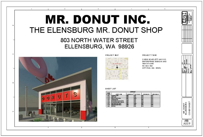
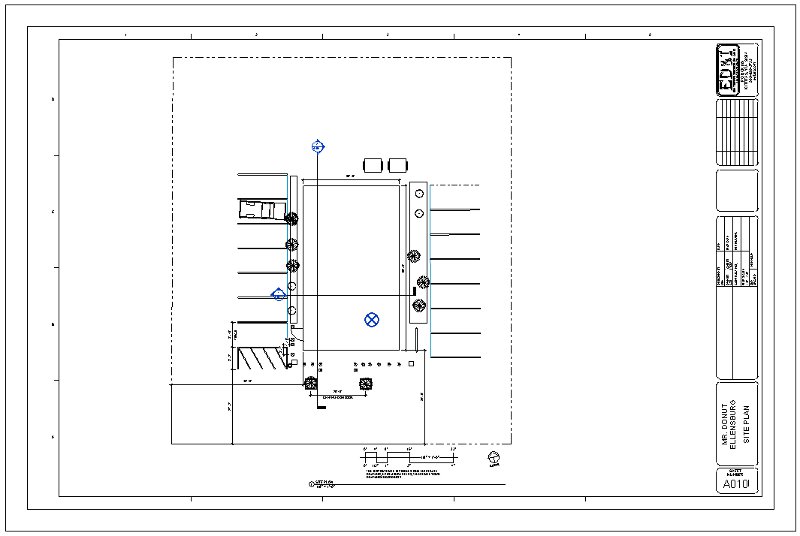

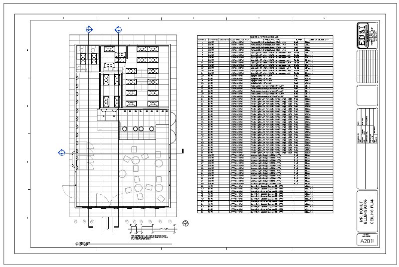
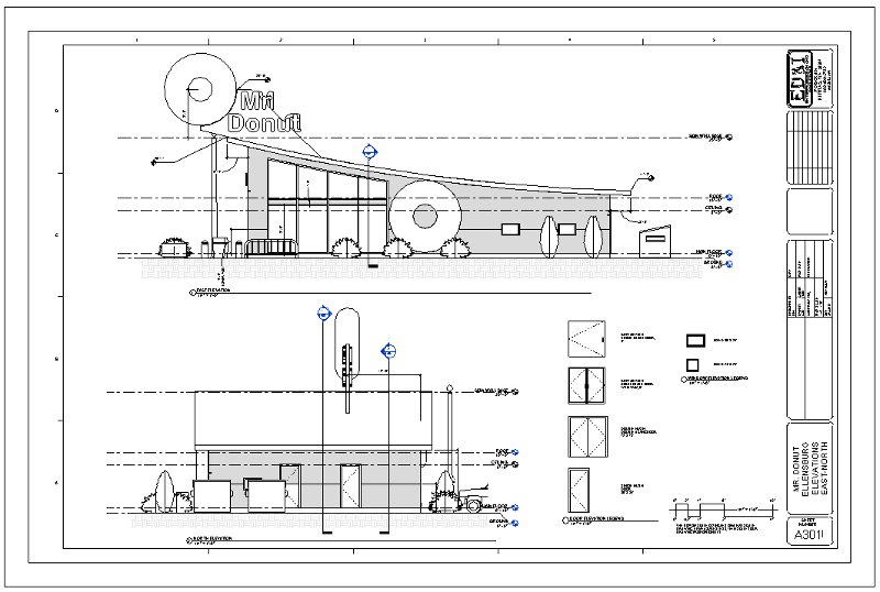

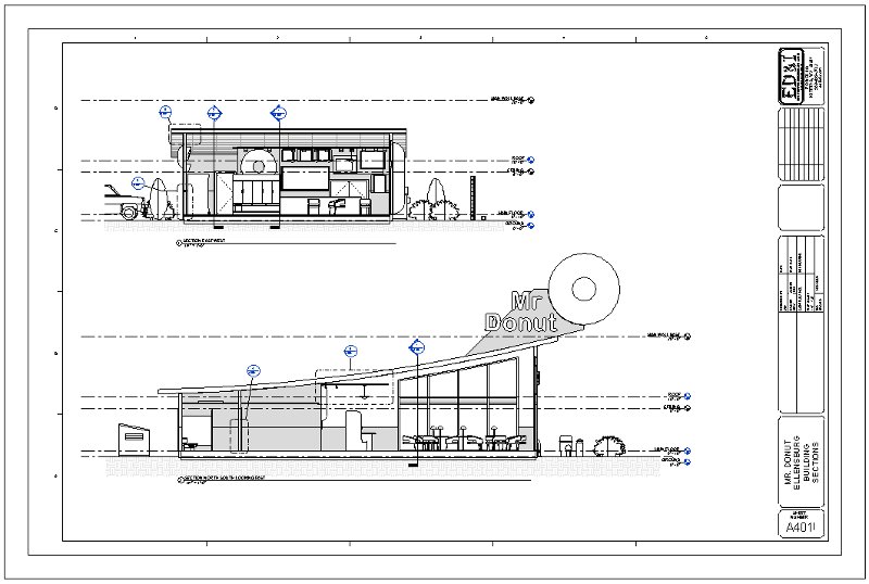
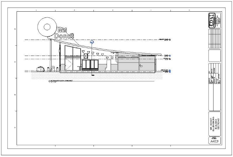
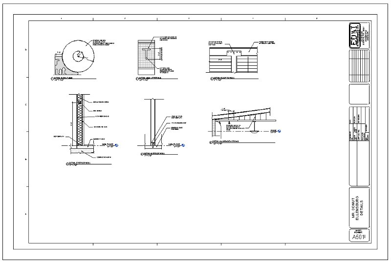
Project Help Back
to Index
Below are some links to
some resources regarding some specific help asked for by some students:
-
How to create some exterior
surfaces with thicknesses like a sidewalk that follows a toposurface.
-
The following links may help:
-
-
How to create a large hanging
clear globe.
-
I would take a modeling family
and make modifications to it by first getting the shape that you want then
resizing it for your needs. I would start with something like a street
lamp. Below are some links:
-
-
How to add color to a Material
Element such as adding color to the Clapboard Siding material whose rendering
qualities are driven by an embedded image. Please click on the following
link for an Instructional Video.
-
-
How to Create a Curved Ceiling.
One of the problems with a curved ceiling is that you can not add ceiling
or hanging lights on this surface. A work around regarding adding
lights on a curved surface works well but takes a lot of steps. First
you make a flat horizontal ceiling on a level of your choosing, probably
the roof level. Don't constrain it to any level with the intent of
moving it up or down vertically and making it very small or narrow horizontally.
Sketch it on the roof level like a small or narrow rectangle in the horizontal
location of your choice and click the green checkmark. Then go to
a section and locate it vertically like right against your curved ceiling.
In a plan view, insert a light on it so that it hangs down vertically.
You can edit the profile of the small ceiling to make it very small just
don't lose it. When hanging a light it does not matter how small
the ceiling is it just has to be a ceiling and the light does not even
need to be attached to it just on the same level once the ceiling host
has been selected. You can also move lights around from different
hosts (ceilings) but this has to be done on a plan view. Select the
light then look in the "Modify | Lighting Fixtures" tab on the ribbon for
this.
Please click on the following
link for Instructional Videos on this subject.
-
-
How to
Create a Skewed Roof and Trim it. First you need to sketch
the roof. If you want to use a different plane to sketch your roof
from insert a Grid line in a plan view (which is really a plane) at an
angle that you desire. On this plane you can sketch your Roof by Extrusion
or use a model wall. With both of these tools you should be able
to get the look you desire.
Please click on the following
link for Instructional Videos on this subject.
-
-
How to
Create Decals and Insert them for Realistic Renderings
Please click on the following
link for Instructional Videos on this subject.
-
-
How do
you manage a large schedule so it can be placed into two sheets.
First
you duplicate the existing schedule by right clicking on it in the Project
Browser and choosing the duplicate option. Now you will have two
schedules (or more) that are identical. Rename both schedules with
consecutive numbers like schedule 1 and schedule 2 and so on... Use
the filter option by choosing that button in the Properties Palette and
filter the Mark of the first schedule to include only those Marks up
to a certain value like perhaps Marks 1 through 50 (use filter less than
or equal to 50). On the second schedule do the same thing
but choose Marks greater than 50 but less than 100. And so forth
Now
you have two unique schedules (or more) that you can insert into sheets
of your choosing.
Please click on the following
link for Instructional Videos on this subject.
|