|
- |
|
|
 |
 |
-
| Week
1:
Design
Assignments due this week:
None
this week but come to the first class of Week 2 prepared by starting the
Design Assignments listed in this section below.
Announcements:
Purchase,
download or otherwise acquire the following book for use in this class.
This book will serve as the primary learning resource for this class:

d
Read
and practice ahead:
Begin
reading and practicing, in the CAD lab, chapters 1 and 2 in your book.
You will be modeling what I call the Book Model which is developed
by you, for practice, as you proceed through the book. Concurrently
you will also be designing your own Project Model (a design of your
choosing) along with the Book Model as you learn various skills
this quarter. Think about what you want to model for your Project
Model, this will be discussed in class on Thursday.
Check
back to this website and the class schedule often for more information
on weekly assignments.
There
will be an evaluation on the first day of class next week on the progress
on your Book Model and Project Model.
|
In
Class exercises and assignment details:
Out of
Class Design Assignment details:
-
Book: Read and practice chapters
1 and 2.
Instructional
Videos:
-
View this
week's Instructional Videos at the following links regarding the subjects
listed below. Please disregard the references in the videos to any
upcoming evaluations. Those comments were intended for another class:
1.
Getting started in Revit
2.
Getting started in Revit, Part 1, Copying Walls
3.
Getting started in Revit, Part 2, Laying Out and Dimensioning Exterior
Walls
4.
Getting started in Revit, Part 3, Laying Out and More on Dimensioning Exterior
Walls
5.
Getting started in Revit, Part 4, Laying Out and Dimensioning Your Interior
Walls
6.
Getting started in Revit, Part 5, More on Laying out and Dimensioning your
Interior Walls
7.
Getting started in Revit, Part 6, More on Laying out and Dimensioning your
Interior Walls Plus Trim Tools
126.
Getting Started-1, Walls, Applying and Modifying Dimensions, Permanent
and Locked
127.
Getting Started-2, Walls, Modifying Dimensions, Reference Plane and Mirror
Functions
|
- |
|
|
 |
|
-
| Week
2:
On the
first day of class this week come to class with the completed assignments
from Week 1 in preparation for your In Class Evaluation (ICE). See
details below. |
In
Class exercises and assignment details:
-
In Class Evaluation (ICE) (2
items). Click here for your Week
2 ICE Evaluation Check List, print this out, fill in the needed information,
follow the instructions and hand it in at the end of the evaluation at
the instructor's desk. On the first day of class this week we will have
an evaluation of the models completed so far from Week 1, the Book Model
and
the Project Model. The evaluation criteria may include:
-
Evaluation Model (10pts)
-
Exterior walls - TBA - Core
Face Exterior orientation (1pt)
-
Permanent and locked dimensions
per the drawing (1pt)
-
Reference Planes - centered
(1pt) Permanent Locked - Equality dimension as shown - show values (1pt)
-
Interior walls, custom wall
from Thursday (1pt), Interior hall - 4 - centered on one of the planes
Permanent - locked dimension (1pt)
-
Interior walls, 3 rooms of your
choice (1pt)
-
Front door, Load Family - TBA
- on one of the end walls 72 x 84 (1pt), centered - Equality dimensions
- show values (1pt)
-
Windows, doors, 6 additional
of your choice - orientation (1pt)
-
Extras and errors
-
Project Model (10pts)
-
Exterior walls, your choice
- Core Face Exterior Permanent and locked dimensions orientation (1pt)
-
Reference Plane, centered (1pt)
Permanent locked - Equality dimension as shown - show values (1pt)
-
Interior walls, Interior hall
width of your choosing, centered on one of the planes Permanent - locked
dimension (1pt)
-
Interior walls, at least 6 rooms
of your choice (1pt) dimension one of the rooms Permanent (1pt)
-
Interior or exterior walls,
one angled and one radius wall (1pt)
-
Doors of your choosing, Load
Family for front door (1pt)
-
Windows, Load Family of your
choosing - level 1 - all sides orientation (1pt)
-
Dimensions, at least 8 on doors
and windows Permanent (1pt)
-
Errors and Extras
Out of
Class Design Assignment details:
-
Book: Read and practice chapters
3 and 4, work on your Project Model.
Instructional
Videos:
31.
Adding Door Like Room Openings.
128.
Arrays-1, Modifying a Linear Array, laying out Windows
129.
Arrays-2, Applying a Linear Array, laying out Windows
130.
Arrays-3, Applying a Radial Array, laying out Reference Planes and Windows
|
- |
|
|
 |
|
-
| Week
3:
On the
first day of class this week come to class with the completed assignments
through Week 2 in preparation for your In Class Evaluation (ICE).
See details below.
New videos
have been added below. |
In
Class exercises and assignment details:
-
In Class Evaluation (ICE) (2
items). Click here for your Week
3 ICE Evaluation Check List (ECL) (link coming soon), print this out,
fill in the needed information, follow the instructions and hand it in
at the end of the evaluation at the instructor's desk. On the first day
of class this week we will have an evaluation of the examples in the book
as applied to a downloaded Evaluation Model and your Project
Model. The evaluation criteria may include:
-
Evaluation Model, download
this model from this link for modifications during the evaluation: Evaluation
Model (20pts)
-
Move the alcove on the east
exterior wall to the north by 25 feet, Constrained (1pt), create a north
south section, symbol on the north end, looking west (2pts), using Edit
Profile cut the original building wall to accommodate this room (3pts)
-
Copy the wall, with door number
5, 10 feet to the east (1pt) dimension this (1pt)
-
Rotate the Work Station Cubicle
90 degrees CW (1pt) and Move it to the south west corner of the room aligned
and locked to the walls (1pt) mirror this to the other side of the room
(1pt), aligned and locked to the walls (1pt)
-
Use the Linear Array command
to copy the window on the north wall in order to layout 6 windows
on this wall with the last window the same distance from the interior finished
face as the first window (3pts) dimension the last window (1pt)
-
Trim or Split the wall to open
the north hallway to the center of the building (2pts)
-
Align the finish face of the
wall with door number 3 on it to the interior finish face of the exterior
wall with the new arrayed windows on it (2pts)
-
Errors and Extras
-
Project Model (30 points total)
-
Views, on your North Elevation,
create three new levels (3pts), rename two of them Roof and Parapet (1pt)
Parapet 3 feet above the Roof (1pt), the other a floor name (1pt) use CAPITALs
(1pt) align and lock to the other levels, place symbols just outside of
the walls, neat and orderly (1pt)
-
Create a floor plan of the above
levels except for the Parapet (1pt)
-
Views, create an Elevation (interior
or exterior) of your angled wall (1pt), proper scope (1pt) descriptive
name in CAPITALs (1pt)
-
Views, create an Interior Elevation
of a long wall with doors and/or windows on it (1pt), descriptive name
in CAPITALs (1pt)
-
Views, create 2 Building Sections
of your choice perpendicular to each other (1pt) descriptive name in CAPITALs
(1pt) symbols close to walls, neat (1pt)
-
Views, create a Wall Section
(1pt) descriptive name in CAPITALs (1pt)
-
Views, create a Detail Section
(1pt) of a Wall Section (1pt) descriptive name in CAPITALs (1pt)
-
Views, create a plan Call Out
in your Level 1 Floor Plan (1pt) of some items of interest similar to the
book (1pt), descriptive name in CAPITALs (1pt), symbols neat and orderly
(1pt)
-
Views, create 2 Camera Views
(1pt) of some details inside your building (1pt)
-
CAPITAL descriptions for all
of your Floor Plans, Ceiling Plans, Elevations and Sections (2pts).
-
Errors and Extras
Out of
Class Design Assignment details:
-
Book: Read and practice chapters
5 and 6, work on your Project Model.
Instructional Videos
|
- |
|
|
 |
|
-
| Design
Assignments due:
On the
first day of class this week come to class with the completed assignments
through Week 3 in preparation for your In Class Evaluation (ICE).
See details below.
New videos
have been added in the Instructional Video section below on methods for
the installation of various roof types. |
In
Class exercises and assignment details:
-
In Class Evaluation (ICE) (2
items). Click here for your Week
4 ICE Evaluation Check List (ECL), print this out, fill in the needed
information, follow the instructions and hand it in at the end of the evaluation
at the instructor's desk. On the first day of class this week we will have
an evaluation of the examples in the book as applied to a downloaded Evaluation
Model and your Project Model. The evaluation criteria may include:
-
Evaluation Model, (20pts),
download this model from this link for modifications during the evaluation
Evaluation
Model (you can practice on last week's model, a new model will
be uploaded before Tuesday, you can copy what you create below and paste
them into your model during the evaluation on Tuesday):
-
Dimension the alcove so that
the distance dimension from the south wall is 27 -0 from core face exterior
to the core face exterior of both walls (1pt), make the interior of the
room (NS) 19 6 from the core face interior of the walls (1pt)
-
Dimensions as a layout tool,
place a string of dimensions using the Align dimension, on the Options
Bar prefer the Center of core and select a string starting at the wall
between rooms 105 and 106 and extend the string to the wall between rooms
108 and 109, 4 dimensions total (1pt), apply the Equality constraint (1pt),
Equality Display set to Value (1pt), all dimensions 10 (1pt)
-
Create a floor slab for the
bottom floor by editing a type of floor family using the following guidelines:
duplicate an existing floor and rename it to 5 Concrete Slab on Grade,
Tile (1pt), change the structure to Concrete, Cast-in-Place gray (1pt),
appropriate thickness (1pt), add a Finish 1 layer on top of the structural
layer (1pt) Tile Mosaic, Gray (1pt) 3/8 thick (1pt)
-
Install this floor on FLOOR
1 Extend into wall (to core) using the interior core boundary (1pt),
alcove also, this will take some editing (1pt)
-
Install the floor Wood Joist
10 - Wood Finish on FLOOR 2 Extend into wall (to core) using
the exterior core boundary (1pt), do not include the alcove, reorient the
span direction to north south (1pt), attach the first floor walls to the
bottom of the floor (1pt), support the floor with the exterior walls (cut
out the wall) (1pt)
-
Reorder the dimensions, annotations
and symbols and eliminate redundancies so that they are neat and orderly
using techniques discussed in class (larger dimension on the outside, no
overlapping annotations on top of each other or on object lines, etc..)
(2pts)
-
Errors and Extras
-
Project Model (30 points total)
-
Dimension your model per guidelines
demonstrated in class, overall dimensions on exterior wall, core face exterior
to core face exterior (1pt), whole units to1/2 foot increments (1pt) exterior
wall jogs core face exterior to core face exterior (1pt), whole units to1/2
foot increments (1pt), 2 interior rooms, length and width (1pt), whole
units to1/2 foot increments (1pt), 6 windows and/or doors from a nearby
consistent reference (1pt)
-
Dimensions as a layout tool,
place a string of dimensions using the Align dimension, on the Options
Bar prefer the Center of core and select a string on at least 5 repeating
elements in your model (doors, windows, components, walls, etc
) (2pts),
apply the Equality constraint (1pt), Equality Display set to Value (1pt),
all dimensions the same value (1pt)
-
Create a custom floor of your
choice using the following guidelines: duplicate an existing floor and
rename it to a name of your choice (use existing conventions) (1pt), modify
the structure (1pt), modify the thickness (1pt), add a Finish 1 layer(s)
on top of the structural layer (1pt) element(s) of your choosing (1pt)
appropriate thickness(es) (1pt)
-
Install this floor on your Level
1 Extend into wall (to core) using the interior core boundary (1pt)
-
Install an existing or custom
floor on FLOOR 2 Extend into wall (to core) using the exterior core boundary
(1pt), reorient the span direction to north south (1pt), attach the first
floor walls to the bottom of the floor (1pt), support the floor with the
exterior walls (cut out the wall) (1pt)
-
Install leader text callouts,
on 4 items in your model that need additional information, 2 segment leaders
(1pt), 3/32 Arial (1pt), CAPITAL lettering (1pt), multiline line text
(1pt), neat and orderly (1pt)
-
Reorder the dimensions, annotations
and symbols and eliminate redundancies so that they are neat and orderly
using techniques discussed in class (larger dimension on the outside, no
overlapping annotations on top of each other or on object lines, etc..)
(2pts)
-
Errors and Extras
Out of
Class Design Assignment details:
-
Book: Read and practice chapters
7 and 8, work on your Project Model.
Instructional Videos
10.
Creating a Roof in Revit, Part 1
11.
Creating a Roof in Revit, Part 2
12.
Creating a Roof in Revit, Part 3
13.
Creating a Roof in Revit, Part 4
14.
Creating a Roof in Revit, Part 5
112.
Fixing a "Flashing Floor" Prior to Inserting a Flat Roof
113.
Inserting a Flat Roof with Elevation Points
119.
How to Create a Skewed Roof and Trim it, Part 1
120.
How to Create a Skewed Roof and Trim it, Part 2
121.
How to Create a Skewed Roof and Trim it, Part 3
|
- |
|
|
 |
|
-
| Design
Assignments due:
On the
first day of class this week come to class with the completed assignments
through Week 4 in preparation for your In Class Evaluation (ICE).
See details below.
New Instructional
Videos have been added in the instructional Video section below.
Videos cover subjects on inserting various components with constraints
and adding stairs.
Instructional
Images have been added below showing some construction techniques related
to residential design. These images show the construction of a foundation,
a floor, floor structure and ultimately the first floor walls and how these
all relate to Revit. |
In
Class exercises and assignment details:
-
In Class Evaluation (ICE) (2
items). Click here for your Week
5 ICE Evaluation Check List (ECL), print this out, fill in the needed
information, follow the instructions and hand it in at the end of the evaluation
at the instructor's desk. On the first day of class this week we will have
an evaluation of the examples in the book as applied to a downloaded Evaluation
Model and your
Project Model. The evaluation criteria may include:
-
Evaluation Model (30pts), download
this model from this link for modifications during the evaluation
Evaluation
Model, (you can practice on last week's model, a new model will
be uploaded before Tuesday)
-
Modify all of the exterior walls
to be Exterior - Brick and CMU on MTL. Stud (1pt), modify the orientation
(1pt), remove constraints if necessary and redefine the changed exterior
dimensions (1pt).
-
Create new floor plans for the
missing floors (2pts)
-
Create a roof by editing a type
of roof family using the following guidelines: duplicate an existing roof
and rename it to Steel Joist 10" - Membrane - Insulated (1pt), change
the structure to: Structure, Steel Bar Joist Layer (1pt), 10 thick (1pt),
and for sheathing Metal Deck (1pt), ½ thick (1pt) add a Finish
1 layer on top of the structural layer (1pt) Roofing, EPDM Membrane (1pt)
3/8 thick (1pt).
-
Install this roof as a Roof
by Footprint for a flat roof on the Roof level (1pts), using the Finish
Face Interior of the exterior walls (1pt).
-
Install a foundation stem wall,
adjust the FLOOR 1 view range to -1 0 (1pt), modify a family to make
the width of your wall 6 (1pt) concrete for the structure (1pt), duplicate
and rename to Foundation 6" Concrete (1pt), T. O. Footing level to -10
(1pt), adjust this view range to -1 0 (1pt), Depth option to T. O.
Footing (1pt), Core Face Exterior (1pt) complete around the perimeter of
the building excluding the alcove (1pt), create a floor plan (1pt)
-
Install a footing under the
stem wall, modify a family to make the width of your footing 12 wide (1pt),
concrete for the structure (1pt), appropriate rename (1pt), adjust your
T. O. Footing view range to a negative -1 0 (1pt), continuous and complete
(1pt).
-
Errors and Extras
-
Project Model (40 points total)
-
Install a pitched Roof by Footprint
on your model or a portion of it, your choice of roof type (1pt), make
this a gabled roof (1pt), define an offset (1pt) from the Finish Face Exterior,
pitch of your choice but not 4/12 or 9/12 (1pt)
-
Install a sloped Roof by Footprint
on your model or a portion of it, your choice of roof type (1pt), define
an offset (1pt) from the Finish Face Exterior, angled like the book (1pt),
pitch of your choice - a standard whole unit to 12 slope (1pt), Attach
Top/Base on all open walls (1pt).
-
Install a Roof by Extrusion
over an exterior doorway of your choosing, your choice of roof type (1pt),
whole unit length (1pt), constrained to the wall (1pt),
-
Install Grid Lines as demonstrated
in class and in the book, numbered ascending from north to south, lettered
ascending from west to east (2pts), grid lines on core face exterior for
the end grids (1pt), specific whole unit lengths for interior grids (1pt),
core centers for exterior wall structures (1pt)
-
Insert a Structural Column,
load Family Concrete Concrete-Round-Column diameter of your choosing
(1pt), at 6 intersections or more, of grid lines (1pt), Height from one
floor to the next (1pt), with offset for floor thickness (1pt), camera
View of these columns (1pt), rename this view to Camera-Columns (1pt).
-
Install a foundation stem wall,
adjust your first floor view range to a negative -1 0 (1pt), modify
a family to make the width of your wall the width of your first floor core
(1pt) concrete for the structure (1pt), appropriate rename (1pt), T. O.
Footing level to -4 (1pt), adjust this view range to Top: 4 0, Cut
plane: 2 0, Bottom: -1 0 , View Depth Level: -1 (1pt), Depth option
to T. O. Footing (1pt), Core Face Exterior (1pt) complete around the perimeter
of your building (1pt) create a floor plan (1pt)
-
Install a footing under the
stem wall, modify a family to make the width of your footing 18 wide (1pt),
concrete for the structure (1pt), appropriate rename (1pt), adjust your
T. O. Footing view range to a negative -1 0 (1pt), continuous and complete
(1pt).
-
Clean up dimensions and annotations
(2pts)
-
Errors and Extras
Out of
Class Design Assignment details:
-
Book: Read and practice chapters
9 and 10, work on your Project Model.
Instructional Videos
9.
Installing Doors and Components Plus the Camera View
33.
Adding Spiral Stairs
34.
Adding Linear Stairs, Part 1
35.
Adding Linear Stairs, Part 2, Modifying and Moving
36.
Adding Linear Stairs, Part 3, Second Floor Cut
37.
Adding Linear Stairs, Part 4, Second Floor Wall and Railing
Instructional Images:
Information on some basic
residential building design elements are shown in the images below.
The images for this week show various elements that go into a simple foundation
and first floor wall construction.
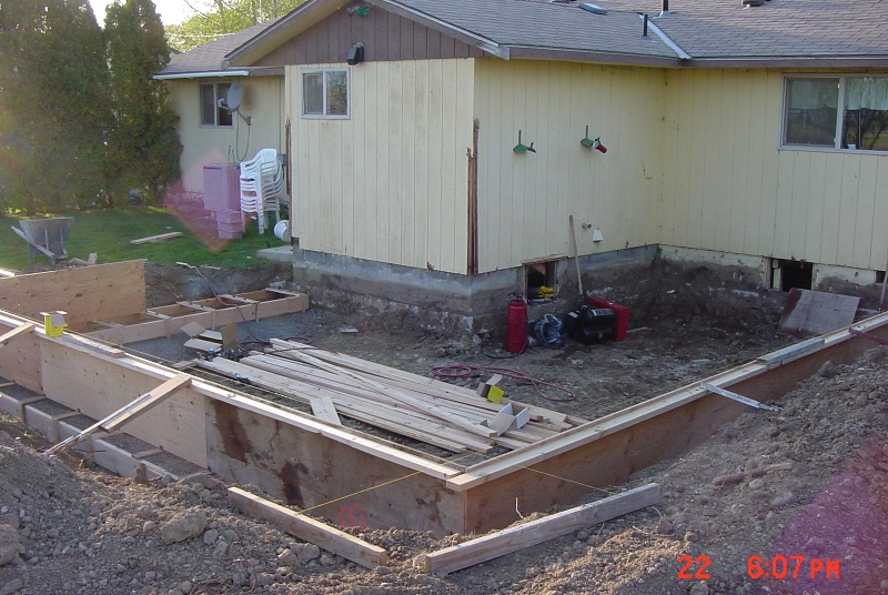
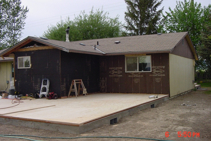
The image below shows the
site work prior to the setting up of the forms for a concrete foundation
footing and stem wall. These foundation elements will be attached
to the existing house providing a bedroom addition.

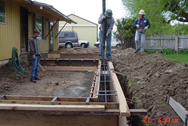
The forms as they were being
set up for the concrete. This will be a "monolithic pour" pouring
concrete for both the footing and stem wall at the same time.
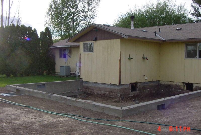
The completed forms on the
front of the house as the concrete was being poured.
The new footing and stem
wall foundation. Notice the embedded anchor bolts sticking out.
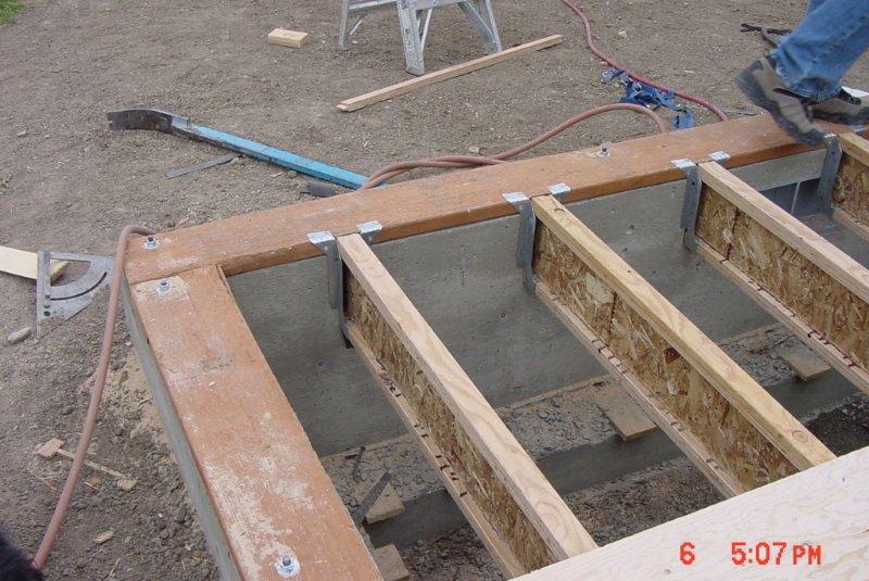
Two days later, the new structural-floor
is constructed on top of the new stem wall foundation. On top of
the stem wall is a 2x6 treated sill plate, bolted down with the embedded
anchor bolts. The sill plate serves as a interface between the wooden
sections of the exterior wall and the concrete foundation. The sill
plate, without treatment, would be subjected to decomposition over time.
The joist hangers attach to this sill plate and joists attach to the inside
of the hangers. The joists serve as horizontal structure for the
structural-floor.
The structural-floor made
of 7 layered plywood at 1-1/4" thick is glued and nailed to the joists.
The sill plate and floor are coplanar to the exterior surface of the stem
wall. The plywood has holes cut into it to accommodate the nuts,
washers and anchor bolts on the sill plate.

The image below shows the
completed structural-floor and is ready for the exterior walls. It
is the top surface of the structural-floor that serves as the first floor
plane. When modeling, the first floor is extruded below this plane
and the first floor walls are extruded above it.
A close-up of the previous
image where the new addition meets the existing house and shows how it
is constructed. Notice how the sheathing and siding cover the edge
of the structural-floor and extends about 2 inches below the top of the
stem wall foundation. This allows water to shed off the siding and
onto the ground (and not into the house). When modeling walls the
"Core Face: Exterior" plane is coplanar to the stem wall, sill plate and
edge of the structural-floor. The "Finish Face: Exterior" plane is
the furthest extend of the wall and includes the 1/2" sheathing (1/2" plywood
or OSB) and 5/8" T-111 siding.

An image of the completed
floor from the crawl space below and includes insulation and ductwork.
This image faces the stem wall shown in the image above.

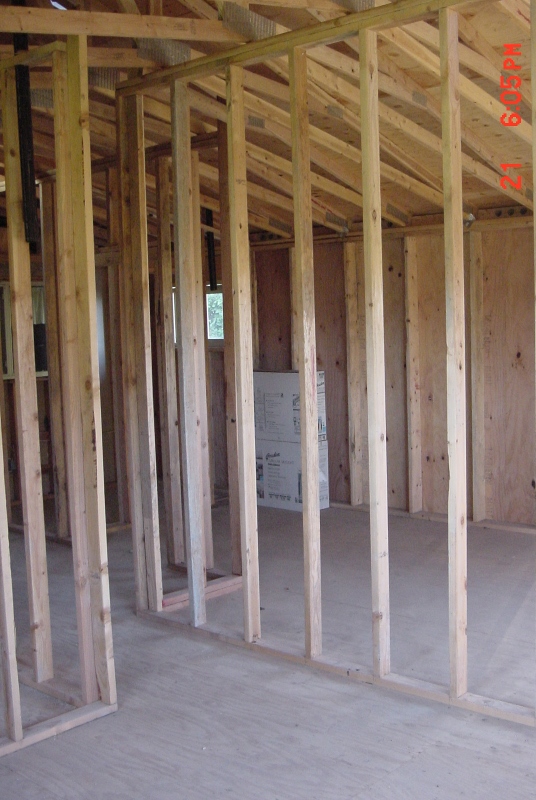
The interior of this space
after interior walls, roof and some plumbing have been installed, facing
the same direction as the image above. It shows interior walls (2x4
construction, 3-1/2" wide) and exterior walls with sheathing (2x6 construction,
5-1/2" wide). The sheathing (1/2" plywood or OSB) is on the outside
of the "Core Face: Exterior" plane and before the "Finish Face: Exterior"
plane so it is on the outside of the core and exterior of the structural-floor,
sill plate and stem wall plane. To finish the exterior of the exterior
walls you would add a layer for the dimensionless wind barrier on the outside
of the sheathing and then siding. On the inside of the core you would
add the structure (2x6 5-1/2" wide). On the interior of the exterior
wall you would add a finish element 1/2" drywall. Occupying the same
space as the structure of the wall (the 2x6) would be the insulation.
The interior wall sandwich would be 1/2" drywall on either side of the
core structure (2x4, 3-1/2" wide) making the wall 4-1/2" thick.
|
- |
|
|
 |
|
-
| Design
Assignments due:
On the
first
day of class this week come to class with the completed assignments through
Week 5 in preparation for your In Class Evaluation (ICE). See details
below.
New Instructional
Videos will be added soon, please check back. |
In
Class exercises and assignment details:
-
In Class Evaluation (ICE) (2
items). Click here for your Week
6 ICE Evaluation Check List (ECL), print this out, fill in the needed
information, follow the instructions and hand it in at the end of the evaluation
at the instructor's desk. On the first day of class this week we will have
an evaluation of the examples in the book as applied to a downloaded Evaluation
Model and your
Project Model. The evaluation criteria may include:
-
Evaluation Model (20pts),
download this model from this link for modifications during the evaluation
Evaluation
Model, (you can practice on last week's model, a new model will
be uploaded before Tuesday)
-
Create a ceiling by editing
and renaming the GWB on Mtl. Stud type to GWB on Wood Stud (1pt), structure
to Structure, Wood Joist/Rafter Layer (1pt), structure to 3 1/2 (1pt).
-
Install this ceiling on the
second floor in rooms 201 through 206 (verify this by a section) (1pt).
-
Install the ceiling 2' x 4'
ACT System in rooms 210 through 213 (1pt), rotate the ceiling grid in
room 213 by 45 degrees (1pt), rotate the ceiling grid in room 212 by 90
degrees (1pt), rotate from the center (1pt), install Troffer lights Troffer
Light - 2x4 Parabolic in every other full grid (checkerboard) in room
212 (1pt), Aligned to the ceiling grids (align the first one, select
it, use the copy command, check multiple on the Options Bar and use a common
end point (like a corner) to copy the rest of them) (1pt).
-
Install stair, FLOOR 1 to FLOOR
2, Run, Straight options (1pt), modify the risers to 18 (1pt), start sketching
in the main hallway in the center of the building facing west, sketch out
9 stairs, provide a landing, then 9 stairs sketching east (1pt), align
and lock the landing to the wall with door 10 on it (1pt), align and lock
the south side of the stairs to the wall with door 11 on it (1pt).
-
Cut out the FLOOR 2 to accommodate
the stairs, L shaped section (1pt) aligned and locked (1pt) cut out the
eastern portion of this floor by about 10 feet (1pt), install a railing
Handrail Pipe around the stairs and the open eastern section of the
floor (1pt), Camera Views named Camera Stair and Camera Railing to
verify your stairs and railing, show the whole item in the view (1pt).
-
Errors and Extras
-
Project Model (40 points total)
-
Create a ceiling by editing
and renaming the GWB on Mtl. Stud type to a type using a wood veneer
on the bottom of the wall board (like the book) and wooden studs (1pt),
GWB on Wood Stud - Wood (1pt), structure to Structure, Wood Joist/Rafter
Layer (1pt), structure to 3 1/2 (1pt) wood veneer of your choice (1pt).
-
Install this ceiling in a large
room of your choice (1pt), provide a camera showing the length of this
room named Camera Wood Ceiling (1pt).
-
Install a 2' x 4' ACT System
ceiling in a hallway of your choosing (1pt), trim boundary so that only
the hall or a small linear portion of the ceiling is showing (1pt), line
the ceiling grids so that there are full panels, that are symmetric, down
the length of the hallway (use your reference plane and an aligned dimension)
(1pt), install Troffer lights Troffer Light - 2x4 Parabolic in every
other full grid down the center of the hall (1pt), Aligned to the ceiling
grids (align the first one, select it, use the copy command, check multiple
on the Options Bar and use a common end point (like a corner) to copy the
rest of them) (1pt), camera view named Camera Hall (1pt).
-
Install straight stairs: One
floor to the next, Run, Straight options (1pt), rename and make 5 foot
wide (1pt), landing (1pt) lined up with itself and symmetric (1pt), aligned
and locked to nearby walls or structures (1pt), looks proper (1pt), extra
credit for extra details here (EC)
-
Install spiral stairs: One floor
to the next (1pt), aligned to nearby walls or structures (1pt), looks proper
(1pt), extra credit for extra details here (EC)
-
Provide an open area on one
floor to the floor below (1pt), install railings on edge (1pt)
-
Install windows on all exterior
walls, at least 3 different types (1pt), exterior doors (2 at least), interior
doors for all rooms (1pt).
-
Install at least 20 different
components like furniture, lights and entourage (2pts), Go the Revit Seek
and download some items and install them (1pt), Go to Revit City and download
some items and install them (2pts), Camera views named Camera Seek and
Camera Revit City showing these items (1pt).
-
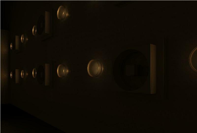
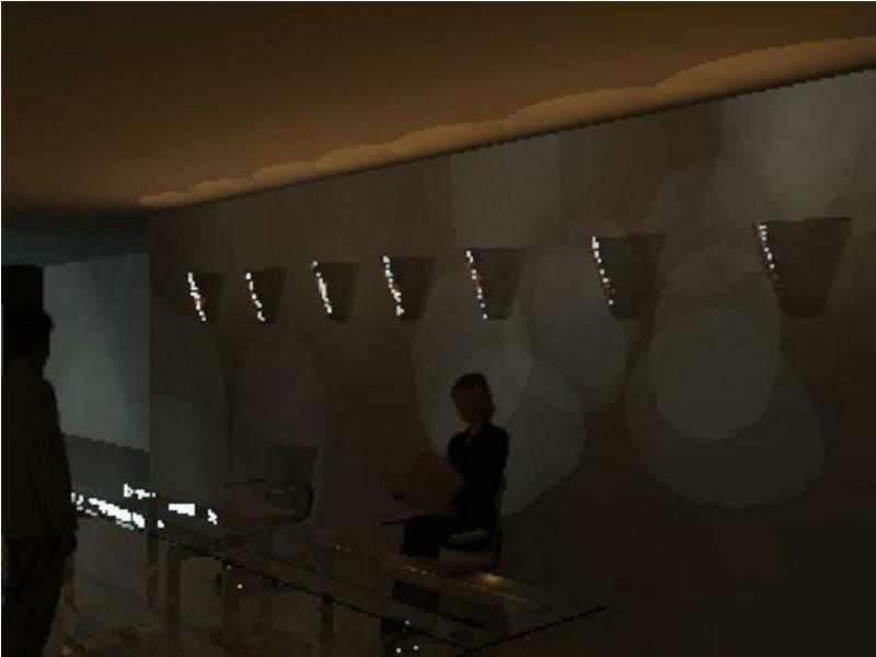
On your long hallway with the
troffer lights insert an Interior Elevation named LONG HALL LIGHT PLACEMENT
of that wall (1pt), place doors if it is a featureless hall, install a
series of sconce lights Sconce Light Uplight on that wall at a consistent
wall height (1pt), and consistent distance from each other and doors (1pt).
-
Camera view down the length
of that hall and name it Camera Hall (1pt), elevation 2, target elevation
10 (1pt) have entourage and furniture in the hall also (1pt), render an
image, Setting Medium (use Draft until you get it right) (1pt), Lighting
Interior: Sun and Artificial (1pt), While the image and dialog box are
still open adjust the exposure if needed. Save image to project (same
name as the camera view).
-
Errors and Extras
Out of
Class Design Assignment details:
-
Read Chapters 15 - Creating
Rooms and Area Plans, Chapter 16 - Advanced Wall Topics.
Instructional Videos
29.
Creating a Room Label
38.
Storefront Curtain Wall, Part 1, Modifying the Host Wall
39.
Storefront Curtain Wall, Part 2, Adding the Wall
40.
Storefront Curtain Wall, Part 3, Modifying the Height, Width Dimensions
41.
Storefront Curtain Wall, Part 4, Modifying Curtain Wall Boundary
42.
Storefront Curtain Wall, Part 5, Moving the Curtain Grid and Mullions
43.
Storefront Curtain Wall, Part 6, Deleting Certain Mullions
76.
Store Front Curtain Wall, Installing a Door
|
- |
|
|
 |
|
-
| Week
7 information: Your first exam will be on
Tuesday of this week. Additional information below. |
Exam
1:
-
Your exam
will be in 2 parts per the class syllabus, a written portion and a design
portion. An evaluation check list for the design portion follows
below.
-
Advice:
-
The design
portion is open source (open book, online resources, etc.).
-
I would
encourage you to create a new file using the parameters below including
setting up your levels, loading components, creating the site and creating
or copying custom walls. You can use this file for the exam.
-
Model
a T shaped residential home, using the following guidelines, New file
using the Architectural Template:
-
Levels,
rename or create FLOOR 1 at 0 0, FLOOR 2 at 9 0, ROOF 18 0,
T. O. FOOTING -4 0 (1pt), Create Plans Views (1pt).
-
Exterior
walls - Exterior - Brick on Mtl. Stud - Core Face Exterior orientation,
location per the drawing (1pt). From Floor 1 to the ROOF levels (1pt),
permanent and locked dimensions (1pt).
-
Reference
Plane - centered down the main hall (1pt). Permanent Locked - Equality
dimension as shown from interior wall centers, show values (1pt).
-
Interior
walls, custom wall from Week 2 Interior Interior 4 ½ Wood Stud
GWB, place as shown (1pt), provide dimensions as shown from the Core face
Exterior of the exterior walls to the center of the interior walls (1pt),
Interior hall - 9 - centered on the plane Permanent - locked dimension
(1pt).
-
Front
door, Load Family Single-Raised Panel with Sidelights as shown, 36
x 84, orientation (1pt), centered - Equality dimensions - show values
(1pt)
-
Interior
doors as shown, 32 x 84 Single Flush (1pt).
-
Opening
in kitchen and living room as a component, load family and modify per drawing
note (1pt).
-
Windows
as shown, load and install your choice of window, at least 3 different
types, each room gets at least one window, corner rooms get at least 2
windows, make the distribution of windows on your house symmetric and attractive,
no tags, no dimensions, consistent sill or head height (1pt), orientation
(1pt), bathroom windows smaller, head height at 5 0 (1pt).
-
FLOOR
1, Install the floor Wood Truss Joist 12" - Carpet Finish - Wood
Finish on FLOOR 1 Extend into wall (to core) using the interior core
boundary (1pt), reorient the span direction to north south (1pt).
-
FLOOR
2, Install the floor Wood Joist 10 - Wood Finish on FLOOR 2 Extend
into wall (to core) using the exterior core boundary (1pt), attach the
first floor walls to the bottom of the floor (1pt), support the floor with
the exterior walls (cut out the wall) (1pt).
-
Install
2 building Sections, NS and EW, appropriate name in CAPITALs (1pt), check
your floors.
-
Install
stair, FLOOR 1 to FLOOR 2, Run, Straight option (1pt), start sketching
in the main hallway in the center of the building facing north, align and
lock the stairs to the east wall in the hall and a dimension of 3 0
locked from the wall at the beginning of the hall (1pt) modify the stairs
to be 4 wide (1pt).
-
Cut out
the FLOOR 2 to accommodate the stairs, cut out the eastern portion of this
floor by about 12 over the living room, aligned and locked (1pt), install
railings Glass Panel - Bottom Fill around the open area of the stairs
and the open eastern section of the floor (1pt). Camera View named Camera
Stair Railing to verify your stairs and railing, show both items in full
in the view (1pt).
-
FLOOR
2, layout rooms of your choosing and install windows per previous requirements,
no dimensions or Room Boundaries (1pt).
-
Install
roof, ROOF Level as a Roof by Footprint for a pitched roof Wood Rafter
8" - Asphalt Shingle Insulated, on the Roof level, 18 overhand, 5/12
pitch (1pt), using the Finish Face Exterior walls (1pt), gabled roof on
2 north east west ends of the house (1pt), Attach Top Base (1pt).
-
Room Boundaries
on FLOOR 1 as shown (1pt).
-
Create
ceilings on the first floor 2' x 4' ACT System in the Kitchen, Office
and Main Hall (1pt), rotate the ceiling grid in the Kitchen 90 degrees
with symmetry, then move the ceiling grids south by 1 0 (1pt), Install
Troffer lights Troffer Light - 2x4 Parabolic in pairs side by side every
other full grid in the Kitchen (1pt), Aligned to the ceiling grids (1pt).
-
Install
a foundation stem wall, adjust the FLOOR 1 view range to -1 0 (1pt),
modify a family to make the width of your wall 12, concrete for the structure,
duplicate and rename to Foundation 6" Concrete (1pt), Depth option to
T. O. Footing (1pt), Core Face Exterior, complete around the perimeter
of the building (1pt), edit the thickness from to 6 from 12, check with
a Building Section (1pt).
-
Install
a footing under the stem wall, modify a family to make the width of your
footing 20 wide, concrete for the structure, appropriate rename (1pt),
adjust your T. O. Footing view range to: Top: 4 0, Cut plane: 2
0, Bottom: -1 0 , View Depth Level: -1 0 (1pt), continuous and
complete (1pt).
-
Provide
a Reveal on the outside of the building, at the same elevation, use the
loaded profile Reveal-Brick Course : 3 Bricks (1pt).
-
Storefront
Curtain Wall, on the eastern LIVING ROOM and FAMILY ROOM wall, about 18
wide, FLOOR 1 to ROOF (1pt), base offset 1 -0, top offset -1 0 (1pt).
-
Site,
from the Site Floor Plan, 0' - 0" elevation points around the building
(1pt), apply the Earth material to the surface (1pt).
-
Reorder
the dimensions, annotations and symbols and eliminate redundancies on FLOOR
1, so that they are neat and orderly using techniques discussed in class
(larger dimension on the outside, no overlapping annotations on top of
each other or on object lines, etc..) (2pts)
General
Notes:
Fix
all errors
No
tags except for room tags
Design
integrity (examples: the stairs should not have a ceiling reveal in a critical
room, windows should not cut into floors and ceilings, a ceiling should
not protrude into a stair well, etc
)
Extra
credit for fixtures, furniture, closets and closet doors, etc
Extra
credit for a good layout and design (considering traffic flow, room sizes
and locations etc
)
Extra
credit of extra items and details beyond what is required as described
above
In Class
exercises and assignment details:
Out of
Class Design Assignment details:
-
Read over Chapter 18, Site and
Topography.
Instructional Videos
-
Please see the Week 8 section
below.
|
- |
|
|
 |
|
-
Design
Assignments due:
Refer
to the information below.
A Final
Project abstract is due for the Week 9 ICE. See details below. |
In
Class exercises and assignment details:
-
No ICE this week.
-
We will discuss Final Project
ideas this week as a class discussion.
-
We will discuss the Final Project
grading criteria as listed in the Final section below
Out of
Class Design Assignment details:
-
Read over Chapters: 11 - "Schedules
and Tags", 12 "Detailing", and 18 "Site and Topography". We will
cover Chapter 19 "Rendering and Presentation" next week.
-
Items from these chapters will
be evaluated during the Week 9 ICE on your Final Project Model.
-
Final Project Abstract, Word
document, in a paragraph or single page maximum.
-
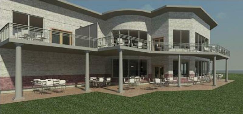
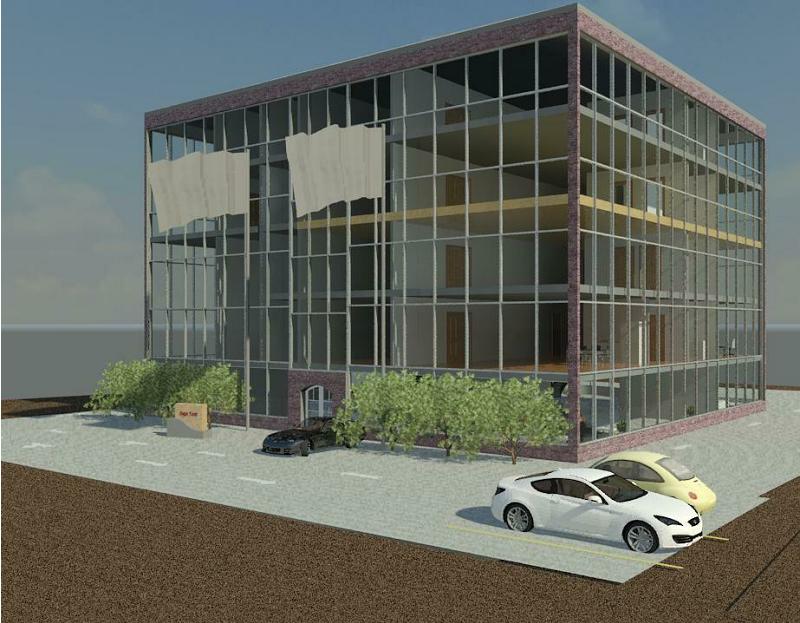
Describe for me what you would
like to design and present to the class as a Final Project. This
abstract will be 10% of your Final Project grade and will be due during
the Week 9 ICE. The abstract will include the following:
-
Description of your project,
as discussed in class, a design of your choice that has some personal interest
to you, such as a residential, industrial or commercial building.
-
Description of the Revit Architecture
toolbar, tool or method that you would like to present to the class as
listed in the Final Toolbar Section below.
-
Description of how the toolbar,
tool or method is related to or aided in your design.
Instructional Videos (more
video links coming soon)
27.
Basement, Toposurface, Building Pad, Part 9, Creating a Toposurface around
the Basement
28.
Basement, Toposurface, Building Pad, Part 10, Creating a Building Pad Around
the Basement
88.
Components to Schedules, Part 1, Alignment and Dimensions, Furniture
89.
Components to Schedules, Part 2, Ceiling Grid and Lights
90.
Components to Schedules, Part 3, Furniture and Entourage
91.
Components to Schedules, Part 4, Entourage, Furniture Tags
92.
Components to Schedules, Part 5, Furniture Schedule
93.
Components to Schedules, Part 6, Door Tags, Door Schedule
94.
Components to Schedules, Part 7, Modify Door Schedule
95.
Components to Schedules, Part 8, Compare Schedules
96.
Components to Schedules, Part 9, Schedules into Sheets
97.
Details and Detail Components Part 1, Detail Call Out and Break Line
98.
Details and Detail Components Part 2, Modifying Break Lines, Lumber and
Insulation Detail Components
99.
Details and Detail Components Part 3, Text Annotations, Detail Lines and
Filled Region
100.
Details and Detail Components Part 4, More on Text Annotations and Insert
into Sheet
101.
Details and Detail Components Part 5, Callout, Repeating Detail, Concrete
Masonry Unit
102.
Details and Detail Components Part 6, Repeating Detail Component, Modifications,
Insert into Sheet
103.
Details and Detail Components Part 7, Legend Component, Options and Text
|
- |
|
|
 |
|
-
| Design
Assignments due: The ICE for this week needs
to be completed before class on Tuesday. Additional information below. |
In
Class exercises and assignment details:
-
In Class Evaluation (ICE) (4
items). Click here for your Week
9 ICE Evaluation Check List, download this now! Print this out, fill
in the needed information, follow the instructions, complete the work,
send the completed files via email by the beginning of the class on Tuesday
and hand in the ECL at the instructor's desk. Have the work as listed
below done before class on Tuesday.
Out of
Class Design Assignment details:
-
Read and practice Chapters 13
- "Creating Specific Views and Match Lines", Chapter 14 - "Sheets" and
Chapter 19 - "Rendering and Presentation".
Instructional Videos
77.
Room Schedule Part 1, Creating the Schedule
78.
Room Schedule Part 2, Settings and Data
79.
Room Schedule Part 3, Data and Key or Room Style Schedule
80.
Room Schedule Part 4, Data and Key or Room Style Schedule
81.
Room Schedule Part 5, Using Sheets and Inserting Items
82.
Room Schedule Part 6, Using Sheets and Inserting Items
83.
Room Schedule Part 7, Modifying Sheet Items
84.
Room Schedule Part 8 Sheets, Insert Room Sched. & Modification
65.
Titleblocks Part 1, Finding a Template
66.
Titleblocks Part 2, Saving the File
67.
Titleblocks Part 3, Modifying Text and Labels with Sizes
68.
Titleblocks Part 4, Moving Text and Lines
69.
Titleblocks Part 5, More on Moving Text and Lines
70.
Titleblocks Part 6, Designing a Logo in AutoCAD
71.
Titleblocks Part 7, More on Logos in AutoCAD
72.
Titleblocks Part 8, More on Logos in AutoCAD with Text
73.
Titleblocks Part 9, Inserting AutoCAD Logos into Revit Titleblock
74.
Titleblocks Part 10, Creating Revit Logos
75.
Titleblocks Part 11, Inserting Logo Images into Revit Titleblock
54.
Camera Views and Image Rendering, Part 1, Location, Managing Sun Path
55.
Camera Views and Image Rendering, Part 2, Location, Sun Path
56.
Camera Views and Image Rendering, Part 3, Location, Sun Path
57.
Camera Views and Image Rendering, Part 4, Sun Path, Camera View
58.
Camera Views and Image Rendering, Part 5, Camera View and Settings
59.
Camera Views and Image Rendering, Part 6, Creating a Ceiling for Lights
60.
Camera Views and Image Rendering, Part 7, Installing Lights in our Ceiling
61.
Camera Views and Image Rendering, Part 8, Rendering and Settings
62.
Camera Views and Image Rendering, Part 9, More Rendering and Settings
63.
Camera Views and Image Rendering, Part 10, Paint Tool
64.
Camera Views and Image Rendering, Part 11, Saving your Rendering
44.
Creating and Modifying a Revit "Walk Through", Part 1, Getting Started
45.
Creating and Modifying a Revit "Walk Through", Part 2, Modifying the Horizontal
Parameters
46.
Creating and Modifying a Revit "Walk Through", Part 3, Modifying the Vertical
Parameters Stairs
47.
Creating and Modifying a Revit "Walk Through", Part 4, Modifying more Vertical
Parameters Stairs
48.
Creating and Modifying a Revit "Walk Through", Part 5, Modifying the Settings
49.
Creating and Modifying a Revit "Walk Through", Part 6, Extending the Path
108.
Graphic Scale Bar
The
following videos are optional and may enhance your Final Project and presentation
122.
Place Decals, Part 1, Decal Types
123.
Place Decals, Part 2, Placing the Decal
|
- |
|
|
 |
|
-
| Design
Assignments due: The ICE for this week needs
to be completed before class on Tuesday. Additional information below. |
In
Class exercises and assignment details:
-
In Class Evaluation (ICE) (4
items). Click here for your Week
10 ICE Evaluation Check List, Print this out, fill in the needed
information, follow the instructions, complete the work, send the completed
files via email by the beginning of the class on Tuesday and hand in the
ECL and drawings at the instructor's desk.
-
Images from this evaluation
will be loaded on the website. As part of an evaluation on Thursday
of this week, the class will vote on what they believe to be the best rendered
images of a well designed project. There will be three prizes:
-
The grand prize will receive
a 30 point extra credit assignment bonus
-
Second place 15 points
-
Third place 10 points.
-
The Grand Prize winner will
also have their Final Project building rendered on a 3D printer (as long
as the model has no interfering solids (build your model correctly per
the class requirements this quarter)).
Out of
Class Design Assignment details:
-
Work on your Final Project
Instructional Videos
107.
Drafting Symbols The North Arrow
136.
Foundation for a Residential Design, Part 1, Top Of Footing Level, Adjusting
the View Range
137.
Foundation for a Residential Design, Part 2, Duplicate Wall for Stem Wall
with Concrete
138.
Foundation for a Residential Design, Part 3, Creating a Footing and Floor
Slab for a Basement
|
- |
|
|
 |
|
-
Final,
Project assignment details (in various sections):
Click here for your:
Final
Project ECL. Print this out and include it with your sheet set.
-
Shortcut links for this
section (or scroll down):
-
Construction Drawings grading
criteria: Back
Your Final Project will have
the following items included in a construction drawing sheet set as described
below. Make certain that you understand your markups throughout the
quarter and incorporate those corrections into your Final Project construction
drawings.
To stay with in the scope
of the requirements of this class your construction drawing sheet set generated
for your Final Project is considered only a sampling of a typical set of
construction drawings and is not intended to include every sheet that would
typically be used for construction purposes. However, if you desire
to generate and print more sheets in each of the sections as described
at the Evaluation Check List (ECL) available at the link below that would
be encouraged but not graded. Some additional sheets may be generated
for extra credit as described in the ECL. The sheet set generated
for your Final Project will not be marked up and will be available in the
Box
at the conclusion of this class for you to use as a portfolio reflecting
your design work from this class.
General information:
-
Number sheets in ascending order
-
Incorporate all of the elements
for these sheets as required from the previous weeks' assignments including
Titleblock items. Title block items also include fields filled in
from your Revit "Project Information" button and your sheet "Properties
Palette" plus your sheet name and number fields (see videos from previous
weeks).
-
General sheet sections are often
numbered in groups like the 200 series for Ceiling plans or the 4.0 (dot)
series for Sections etc... . The series below uses hundreds
as the delimiter but you may choose what ever criteria you desire as long
as it makes sense and is sequential. Architectural drawings may also
have an "A" along with the number. Below are some section suggestions.
-
Cover Sheet, no number, 000,
001, 0.1, 0.01, etc...
-
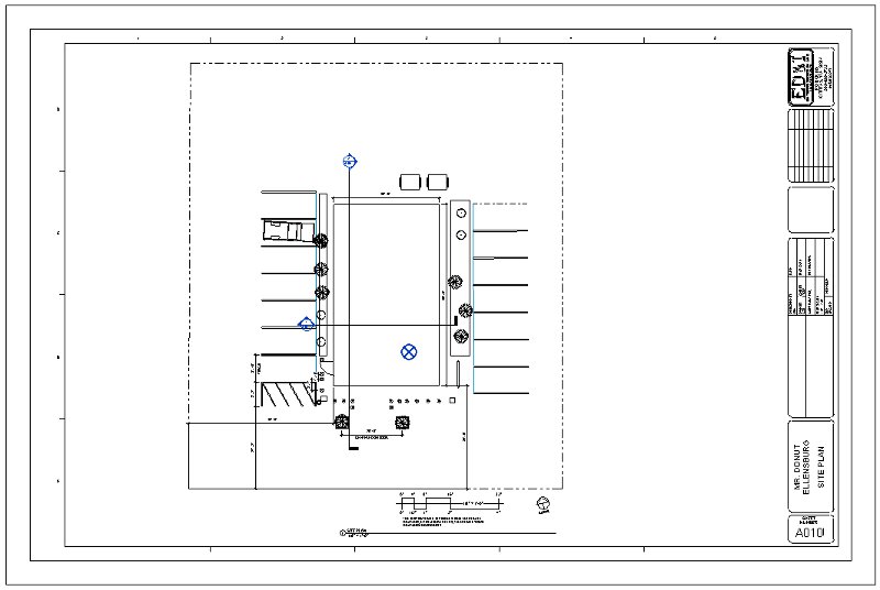
Site Plan 010 series
-
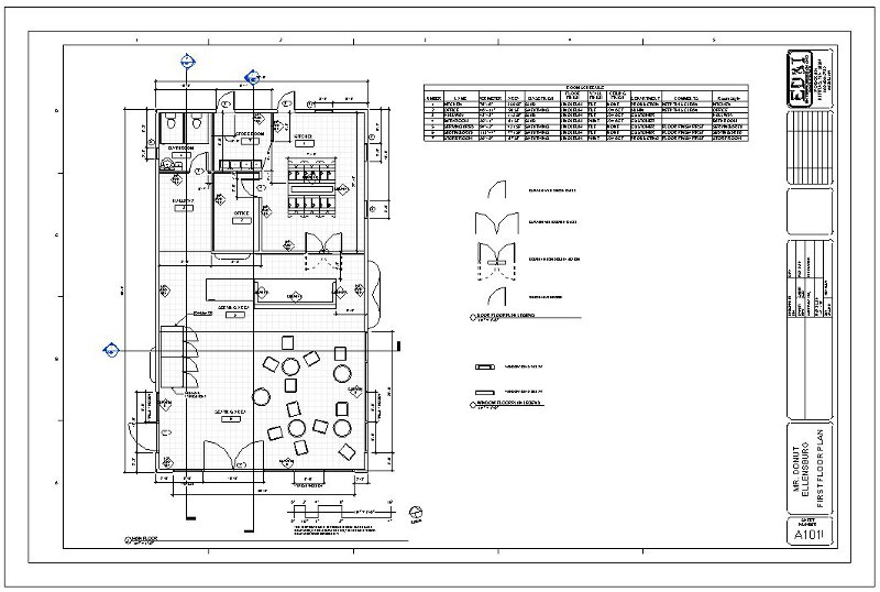
Floor Plans 100 series
-
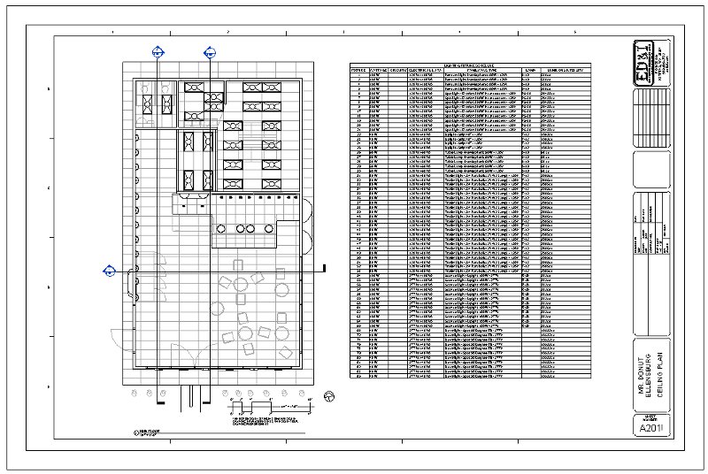
Ceiling Plans 200 series
-
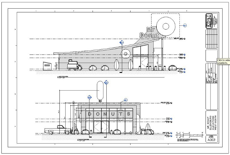
Elevations 300 series
-
Sections 400 series
-
Schedules and/or Legends 500
series
-
Details 600 series
-
Notes:
-
Legends and schedules may be
included on other relevant sheets if there is room.
-
If a numbered sheet series is
blank then move up the numbering to maintain the sequence.
-
Extra credit for extra effort
and items, and may include, sheet notes and annotations that better explain
elements of your project, extra schedules, legends and similar items.
-
See some sheet examples at the
end of this section.
Refer to the Final Project ECL
for addititional information.
-
Printing Requirements:
Back
Print your sheet set before
the Final Project presentations on Wednesday.
Refer to the Final Project
ECL for addititional information.
-
Problem
Printer Solutions:
Back
Below is a solution
for some of the printing problems in the lab (this information may change,
please check back).
Regarding images being flipped
or missing on the plotter and printer, use the following procedure:
-
Create a pdf document instead,
using the print command.
-
Instead of printing to one of
the three lab printers download and install the cutepdf
writer or printer at the following link: cutepdf
-
Choose the cutepdf printer
-
Go to the Printer properties
button and select the ARCH D paper size, center and scale to 100%
-
Pick a file save location in
your Commercial Project folder
Your standard 36" x 24" sheet
should now be generated as a 36" x 24" sized pdf document
-
Open the folder where this pdf
is and open the file. Print this using the HP6015 printer for half
sized prints or the HP800 plotter for full sized prints using the settings
described above.
As a final check measure a known
length with your Architectural Scale and/or measure your Graphic Scale
Bar.
Regarding getting your sheet
to fill up the page or printing to full scale on the plotter, or the plotter
does not recognize the ARCH D sized paper, follow the procedure below:
-
To print on the HP800 plotter,
choose the following settings
-
Put in the 24" sized paper roll
-
Through Revit,
-
Create a custom size 36 x 24
sheet size
-
Click Setup button
-
Choose, Center, Landscape, Zoom
to 100%
-
Click the printer Properties
button
-
Check the "Autorotate" button
-
Select the roll size of 24"
Start printing and if its not
right go to the plotter and "cancel" it, check and change your settings
and start again.
As a final check measure
a known length with your Architectural Scale and/or measure your Graphic
Scale Bar.
-
Sample Sheet Set: Also
click on the links below for pdf documents of various sheet examples shown
in class. Back
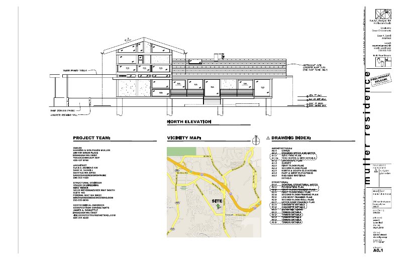
Sage Design, sample Cover
Sheet, Detail Sheet and Titleblock

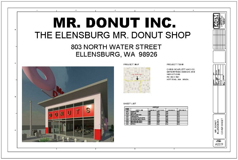
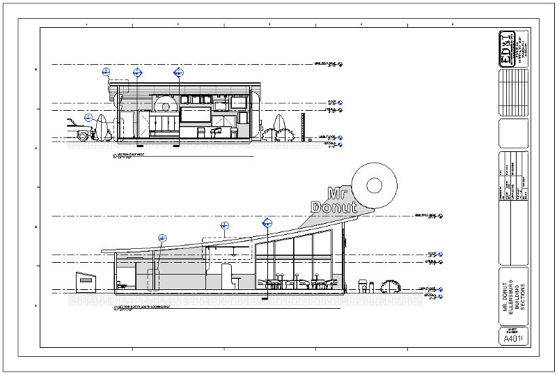
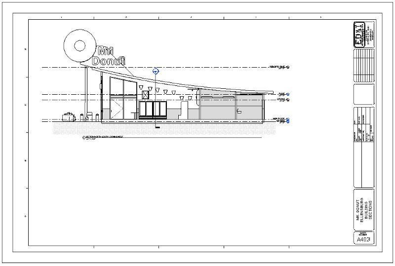
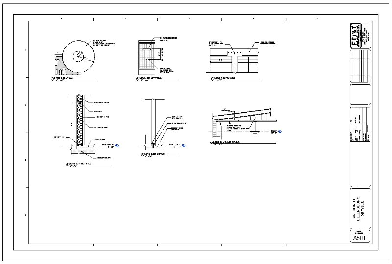
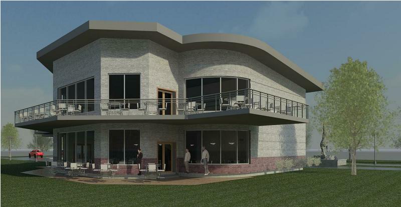
Mr. Donut, sample Commercial
Project

-
Project Presentation, as
evaluated by your peers: Back
You may use the
following guidelines or something similar for your presentations:
-
Introduction, provide your name,
major and class position (senior, junior, etc...)
-
Introduction to your project,
project name and service provided
-
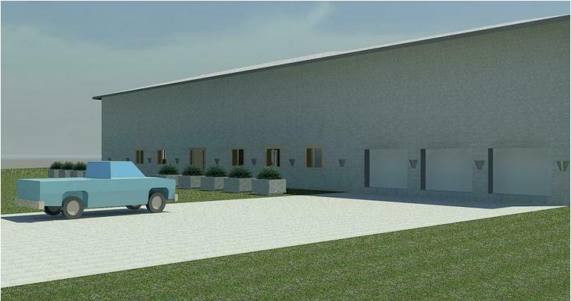
Tour
-
Start with a 3D view, the floor
plan or other view. Since these are commercial or residential projects
your design should be facilitating the interaction between customers and
staff, or how a person will navigate through different parts of the house
-
Show how a customer or visitor
will approach the building (street and parking)
-
Show how a customer or visitor
will enter the building and interact with staff or find their way around
the house
-
Show and explain the service
or entry area
-
Show the support areas or in
a house the more public areas of the house and the flow of traffic through
related rooms.
-
Show auxiliary areas or in a
house, the more private rooms, office and storage
-
Move on through the model and
demonstrate any features that you think are significant in your project
that may not be apparent in other student projects or that have not been
demonstrated in class
-
Show elevations, sections, 3D
view, camera views and/or renderings of any features that you feel help
demonstrate how your building functions and the features associated with
that function
-
Show the more significant components
used and where they came from
-
Show a brief Walk Through, 1
minute maximum with narration
-
Describe a toolbar, function
or modeling technique unique to what has been demonstrated in class and
that you have applied to your project. (Toolbar choices below)
-
Name the toolbar or function
-
Demonstrate the tool(s) function(s)
or methods(s)
-
Demonstrate the steps involved
-
Demonstrate different options
-
Demonstrate the effects of the
different options
-
You will graded by your peers
on the Presentation Feedback Form on how much they learned from your presentation.
-
Conclusion:
-
Summary
-
Ask for questions
-
Ask for suggestions i.e. "how
can I model this differently or better"
-
I would invite interaction and
would encourage raising your hand to interrupt for explanation or to share
a different technique.
Keep your presentation to around
5 minutes total, the toolbar presentation about 2 minutes, practice this!
Points taken off for over or under this time.
-
Presentation Toolbar Choices.
Back
Demonstrate a Revit toolbar,
function or method that has not been covered in this class and demonstrate
that to the class during your presentation. A good source for ideas
is the textbook. There have been sections of the book that have been
skipped that cover details that exceed the scope of this class but still
may be relevant for your particular project. Below is a list of some
of those sections; the notation below includes the name of the section,
the chapter number and page number. Back
-
Editing Wall Joins 2-82
-
Displaying Wall Joins 2-86
-
Disallowing Wall Joins 2-88
-
Walls, Editing the Cut Profile
2-90
-
Walls, Placing Openings in Your
Walls 2-101
-
Views, Splitting a Section Segment
3-150
-
Splitting Floor Materials 6-300
-
Floors, Adding Alternative Materials
6-301
-
Floors, Splitting and painting
6-304
-
Pitching a Floor to a Drain
6-309
-
Floors, Creating Shaft Openings
6-314
-
Roofs, Tapering a Roof and Adding
Drains 6-330
-
Roofs, Adding a Roof Dormer
6-370
-
Structure, Using Structural
Framing 8-402
-
Adding a Beam System 8-407
-
Adding Bracing 8-409
-
Structure, Piers and Spread
Footings 8-426
-
Ceilings, Creating a Plan Region
9-444
-
Ceilings, Creating a Sofit 9-455
-
Stairs, Modifying Boundaries
10-501
-
Stair and Railing modifications
(various modifications as described in chapter 10)
-
Stairs, Landing Railings 10-515
-
Creating a Winding Staircase
or sketching a stair 10-522
-
Stair and Railing Families 10-539
-
Stairs, Creating a Custom Railing
System 10-542
-
Creating Custom Stairs 10-546
-
Stairs, Adding a Custom Landing
10-552
-
Stares, Adding a Gooseneck 10-554
-
Stairs, Adding a Raised Panel
Stile and Rail System 10-558
-
Schedules, Creating Material
Takeoffs 11-591
-
Schedules, Creating a Calculated
Value Field 10-595
-
Schedules, Adding Symbols to
a Legend 10-606
-
Schedules, Taggin by Material
10-624
-
Schedules, Creating CustomTags
10-626
-
Schedules, Keynoting 10-636
-
Detailing, Working with Line
Weights 11-646
-
Detailing, Modifying Filled
Regions 11-660
-
Detailing, Creating Blank Drafting
Views 11-693
-
Rooms, Adding a Color-Fill Plan
15-781
-
Rooms, Creating an Area Plan
15-785
-
Advanced Walls, Creating Compound
Walls 16-792
-
Advanced Walls, Adding Wall
Sweeps 16-801
-
Advanced Walls, Modifying a
Wall's Profile in Place 16-804
-
Advanced Walls, Creating Stacked
Walls 16-812
-
Advanced Walls, Adding a Blank
Curtain Wall 16-819
-
Advanced Walls, Adding a Wall
to a Massing Object 16-829
-
Families, Creating Families,
3D modeling using the Revit interface as described in Chapter 17
-
Site, Creating a Toposurface
by Instance 18-901
-
Site, Creating a Graded Region
18-910
-
Rendering techniques not covered
in class as described in Chapter 19 or developed elsewhere.
-
Presentation Feedback Forms:
Download
sample form page at this link: Presentation
Feedback Form. Back
Presentation Feedback Form
booklets will be handed out at the beginning of the class and will include
the following criteria:
-
Sign your name on the cover
only
-
Fill in the student's name,
on each page in the book, in the space provided
-
Suggestions are voluntary and
welcome, constructive comments only
Provide a fair evaluation
on your peers projects based on the listed criteria (points off for a
blank page or a page filled in with all 10s or all 0s showing a lack of
commitment to the task at hand). Circle the number that you feel
best describes your peer's placement in each evaluation section.
-
Project Design grading criteria:
Refer to the Final Project ECL for addititional information.
Back
-
Project Help Back
Below are some links
to some resources regarding some specific help asked for by some students:
-
How to create some exterior
surfaces with thicknesses like a sidewalk that follows a toposurface.
-
The following links may help:
-
-
How to create a large hanging
clear globe.
-
I would take a modeling family
and make modifications to it by first getting the shape that you want then
resizing it for your needs. I would start with something like a street
lamp. Below are some links:
-
-
How to add color to a Material
Element
such as adding color to the Clapboard Siding material whose rendering qualities
are driven by an embedded image. Please click on the following link
for an Instructional Video.
-
-
How to Create a Curved Ceiling.
One of the problems with a curved ceiling is that you can not add ceiling
or hanging lights on this surface. A work around regarding adding
lights on a curved surface works well but takes a lot of steps. First
you make a flat horizontal ceiling on a level of your choosing, probably
the roof level. Don't constrain it to any level with the intent of
moving it up or down vertically and making it very small or narrow horizontally.
Sketch it on the roof level like a small or narrow rectangle in the horizontal
location of your choice and click the green checkmark. Then go to
a section and locate it vertically like right against your curved ceiling.
In a plan view, insert a light on it so that it hangs down vertically.
You can edit the profile of the small ceiling to make it very small just
don't lose it. When hanging a light it does not matter how small
the ceiling is it just has to be a ceiling and the light does not even
need to be attached to it just on the same level once the ceiling host
has been selected. You can also move lights around from different
hosts (ceilings) but this has to be done on a plan view. Select the
light then look in the "Modify | Lighting Fixtures" tab on the ribbon for
this.
Please click on the following
link for Instructional Videos on this subject.
-
-
How to
Create a Skewed Roof and Trim it. First you need to sketch
the roof. If you want to use a different plane to sketch your roof
from insert a Grid line in a plan view (which is really a plane) at an
angle that you desire. On this plane you can sketch your Roof by Extrusion
or use a model wall. With both of these tools you should be able
to get the look you desire.
Please click on the following
link for Instructional Videos on this subject.
-
-
How to
Create Decals and Insert them for Realistic Renderings
Please click on the following
link for Instructional Videos on this subject.
-
-
How do
you manage a large schedule so it can be placed into two sheets.
First
you duplicate the existing schedule by right clicking on it in the Project
Browser and choosing the duplicate option. Now you will have two
schedules (or more) that are identical. Rename both schedules with
consecutive numbers like schedule 1 and schedule 2 and so on... Use
the filter option by choosing that button in the Properties Palette and
filter the Mark of the first schedule to include only those Marks up
to a certain value like perhaps Marks 1 through 50 (use filter less than
or equal to 50). On the second schedule do the same thing
but choose Marks greater than 50 but less than 100. And so forth
Now
you have two unique schedules (or more) that you can insert into sheets
of your choosing.
Please click on the following
link for Instructional Videos on this subject.
|


.jpg)
.jpg)
.jpg)
.jpg)
.jpg)
.jpg)
.jpg)
.jpg)
.jpg)