Click on the following links
Click on the following links for some perspective on the founding of SolidWorks: Trailer
for the Movie "21"
|


| - | ||
 |
 |
Week
1:
Read the introductory sections of both textbooks. Also read and model Lessons 1&2 in the SG textbook and read and model Project 1 in the ED textbook up to page 1-64 for the Plate. |
For next Monday and Tuesday we will have an evaluation of the models completed so far. The part in the SG book Lesson 2 (name this the Box) and the Switch Plate in the task section. The evaluation criteria will include:
Box
- Completeness, 2 points
- Demonstrations
- Fully defined sketch with dimensions, 4 points,
- Extrude, Feature Fillet, Shell, Extrude Cut, 1 point each.
- Completeness, 2 points
- Demonstrations
- Fully defined sketch with dimensions, 4 points,
- Extrude, Feature Chamfer, Shell, Extrude Cut, 1 point each.
| - | ||
 |
|
Week
2:
Lecture: An evaluation of your models from last week will be on Monday or Tuesday depending on your class. Click on the following link for your Evaluation Check List (ECL). Print this document out and have it ready for your evaluation before class. Call me if you have any troubles on your assignments, do not come to class unprepared! We will cover all of the models due this week. |
For next Tuesday we will have an evaluation of 2 of the 4 models that we have modeled so far in a similar format as this week. The evaluation criteria will be similar to the following:
- Completeness, models are finished with all of the features shown in the examples or in class. (1 point with 1/2 point off for each missing feature)
- Dimensions, I will be looking for proper dimensions on your sketches (2 points with 1/2 point off for each missing dimension)
- Fully Defined, your model sketches will be fully defined (lines are black) (1 point)
- Feature Names, rename features to better describe what that feature does (2 points with 1/2 point off for each unnamed feature). See example below.
- Origin, the origin will have to be somewhere placed specifically in the model either in the center of your object or where the examples in the book show it to be located (1 point).
- Modeling modifications (3 points)
- Extra credit, 1/2 point for each fully defined feature or element.

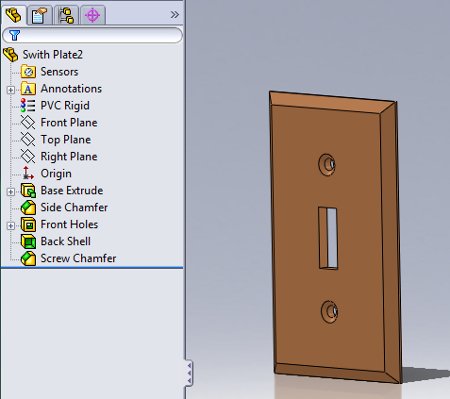
The image below shows some more accurate dimensions for your Outlet Cover. Use inches as your units precision to 3 units after the decimal. Use a fillet instead of a chamfer.

Assignments:
Complete the Plate, Blocks
and Cosmetic Thread from the ED book.
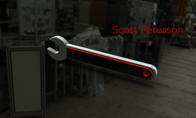
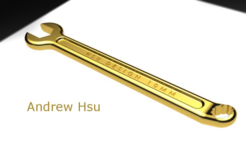
Complete Tutor1 and the Wrench in the SG book.
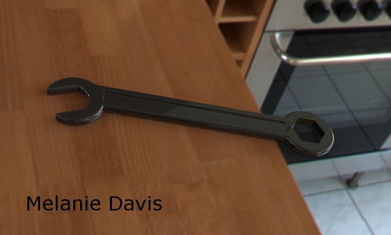
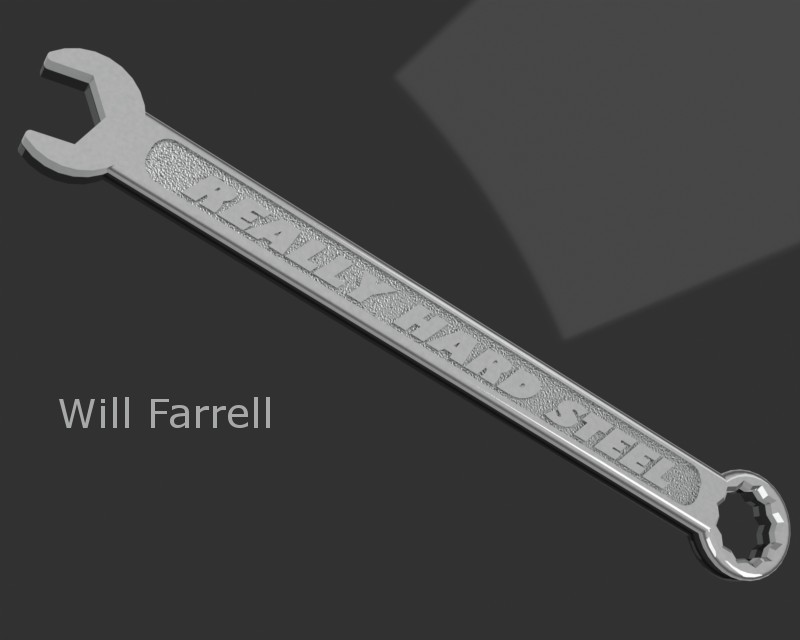
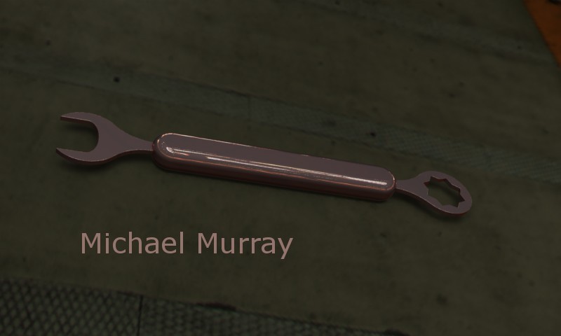
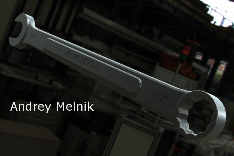
Information on the Wrench: Model a wrench, in a manner you see fit, must be a specific size and an angled head (around 5 to 7 degrees), choose a metallic material. A demonstration of some modeling techniques will be on Wednesday and Thursday.
| - | ||
 |
|
Week
3:
Lecture: We will introduce PhotoView 360 plus cover some of the models for your assignments for this week. Read the section on the models that need to be designed for next week's assembly design assignment below. |
Evaluation:
- Click on the following link for Monday's Evaluation Check List (ECL),
- Click on the following link for Tuesday's Evaluation Check List (ECL),
- print your checklist and fill it out before class.
- You will need to hand in three items similar to last week's evaluation:
- The volume of the part in the body of the email, the SolidWorks part file of the Block modeled in class, and the the SolidWorks part file of a model completed last week to be announced in class.
- PhotoView 360 rendering of your wrench, high resolution, 800 pixels wide, jpg format, send via email by Friday.
- Tutor1
- Modify this design so that the front boss and hole are not shelled.
- Flat Bar
- Complete the four configurations of the Flat Bars (3, 5, 7 and 9 (and more for extra credit)) in the ED book. A demonstration on configurations and design tables will be held in class.
- Assembly Models: Design at least 3 unique parts with the expectation of assembling them for next week's Design Assignment. The assembly, other than the base, must be able to move, rotationally or translationally.
- Base
- One part has to be a base feature to be fixed to the Origin in the assembly.
- To have a round or rectangular hole(s) or slot(s) for the insertion of additional parts
- Hole Wizard holes in the base for mounting to some structure
- Part1
- To be inserted on the base
- Must fit in a slot or hole on the Base as described above
- Part2
- To be inserted on the Base or on Part1
- Hole Wizard feature on a part other than the Base
- Linear or circular pattern
- Feature using the Slot Sketch Entity on a part
Fasteners, connectors
and pins are not appropriate parts for this assignment but can be used.
A minimum level of complexity
is required for each part.
Include the following features
on at least one of the parts above:
| - | ||
 |
|
Week
4:
Lecture: We will cover Assemblies this week. |
Evaluation:
- Click on the following link for this week's Evaluation Check List (ECL),
- print your checklist and fill it out before class.
- You will need to hand in items similar to previous weeks' evaluations:
- The volume of the part in
the body of the email, the SolidWorks part file of the Modify Evaluation
modeled
in class, and the the SolidWorks part file of a model(s) completed last
week to be announced in class and modified.
- Tutor2 per the SG book
- Tutor Assembly per the SG book
- Mechanical Claw per the SG book, see the Student Resources page for the files that you will need. Download and extract on your storage medium the zip file named "SG-Lesson04 as a zip folder"
- Guide Rod assembly in Project 2 in the ED book
- Exercise 2.6 Linkage Assembly in the ED book
- Your own assembly using your Assembly Model parts created from the previous week's assignments.
- Assemble these parts together with some flexibility
| - | ||
 |
|
Week
5:
Lecture: We will cover Drawings this week and discuss your Final Projects, be prepared to discuss your ideas with the class. |
Evaluation:
- Click on the following link for this week's Evaluation Check List (ECL),
- print your checklist and fill it out before class.
- Download the following zip folder of parts for your assembly evaluation, Week-4-Assembly.zip.
- Put together your assembly per the instructions on the drawing provided in class prior to the evaluation.
- You will need to hand in items similar to previous weeks' evaluations:
- Pre Evaluation advice:
- Make certain that you have completed all of the assignments from Week 4, you will be using two of these models in the assembly for this evaluation, one will be the Flat Bar.
- For the Shell feature, explore this and know how to use the second option dialog called "Multi-thickness Settings". You will be picking a different face and making that face thicker than the others selected in the "Parameters" dialog.
- Know the Straight Slot or Centerpoint Straight Slot Sketch Tool
- The mass of the part that
you will be modeling in the body of the email
The SolidWorks part file that you will be modeling in class
The the SolidWorks Assembly file
The SolidWorks parts that you downloaded
Your own parts and assembly files for your Assembly Model
- Project 3 in the ED book
- Assembly Model part drawing of your choice similar to the drawing of the Guide in Project 3 in the ED book, hand in by Friday by 5pm, in the Box.
- Include the following:
- Three standard views, an Isometric view and Section view
- All views with view titles
- All views with the proper Display State as demonstrated in class
- Other views and details for extra credit
- Dimensions, organized and visible on the Dimension layer
- Title Block updates as demonstrated in class
- The Switchplate and Bearing Block assemblies in Lesson 5 of the SG book
- Download the files you will need from the Student Resources page.
- Task 2 in Lesson 6 in the SG book after we create your Drawing Template file in class
- Modify your assembly using the Assembly Model parts and assembly created from the previous weeks' assignments. Add to this assembly the following:
- Use fasteners from the Tool Box in your holes and Hole Wizard holes
- Provide a Motion Study
- Provide an Exploded View
| - | ||
 |
|
Week
6:
Examination
on Monday and Tuesday, details below
|
Assignments:
- Final Project abstract, printed and in the Box, or sent via email by 5pm on Friday, see the Student Resources page for information. Click on the following link for additional information: Final Project Abstract Information
- Project 4 in the ED book, skip the part on creating a new template file and on Mold Tools
- Project 4, Exercise 4.9
- Project 4, Exercise 4.10
- Lesson 9 in the SG book including the Candle Stick and Candle assembly, Mug and Top, skip the part on the Outlet Cover.
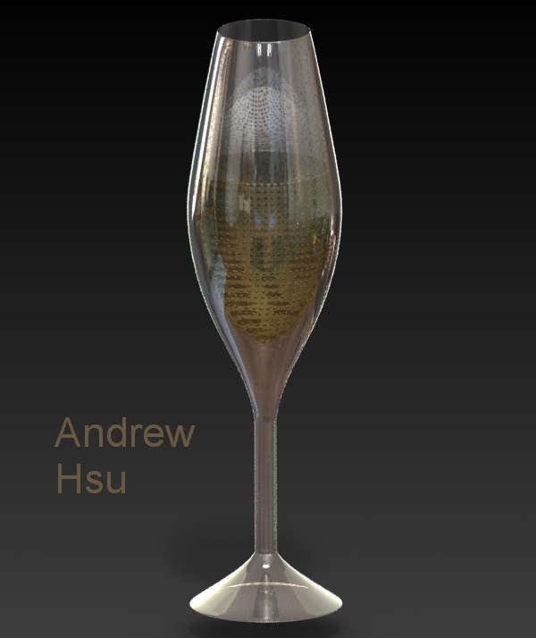
- Assignments to send in by Friday by 5pm include 2 images of revolved features and a printed drawing. The images include:
- Your Candle Stick assembly, make this unique
- A part using a revolved feature of your choice (bowls, glasses, wine glass, cups, trays, tops, lamps, etc...)
- The image assignments include the following requirements:
- Use PhotoView 360 or PhotoWorks in SolidWorks
- High resolution option
- Must have a scene and lights
- 800 pixels wide
- jpg format (check your file extensions *.jpg)
- Extra credit for extra effort
- The Drawing of your design above (printed and in the Box by 5pm on Friday) and include the following requirements:
- A sized sheet landscape (create a new template file in class)
- Display the following views:
- Front View showing Hidden Lines Visible HLV
- Top View with Hidden Lines Removed HLR
- Right View with Hidden Lines Removed HLR
- Isometric View with Shaded With Edges SWE
- Add views titles under each view on the green Sheet Notes layer
- Include all appropriate dimensions on the red Dimension layer
- Fill the usual values in the Title Block (as iterated in Project 3) including:
- your name
- part name
- file name
- company name
- units of measure
- dimensioning standard
- confidentiality statement (filled in with your company name)
Examination:
You will have your first examination the first class day this week in 2 parts. The written portion will be per the syllabus and the design assignment portion will be as described below:
Model a Hand Truck (portion of one) using parts and assemblies with Tool Box items and models from 3D Content Central similar to the image below
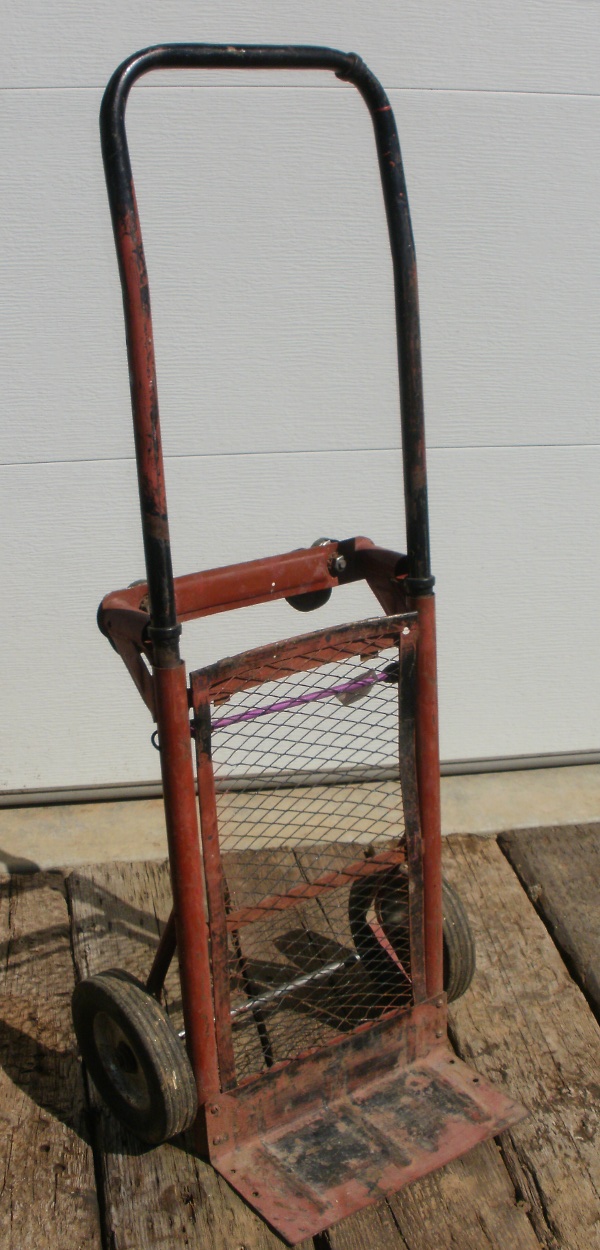
- Model 3 parts, download 2 parts from the website, download a caster from 3D Content Central and put all them together into a sub-assembly of a Hand Truck , the parts, instances and descriptions include:
- Base Flange (1) your model in class
- Pole Supports (tubing) (2) your model before class
- Back Plate, with a Cosmetic Pattern (1) your model before class
- Back Plate Support (4) download
- Horizontal Wheel Mount (1) download
- Caster with a 3/8" stem download from 3D Content Central
- You will also be using Tool Box items such as nuts, bolts and washers
- The models will include material selections, Hole Wizard features and appearance modifications
- Some part details will be available on this website for modeling prior to the examination.
- Other details will be made available during the examination.
- General notes
- Use two colors as a theme throughout your design and apply those to your parts except for the Tool Box and 3D Content Central items.
- All holes are symmetrical if they appear so
- Use the precision (units after the decimal) as shown in the images and drawings or as directed in class
- Use all of the conventions that you have been evaluated on throughout the quarter so far (see previous ECLs).
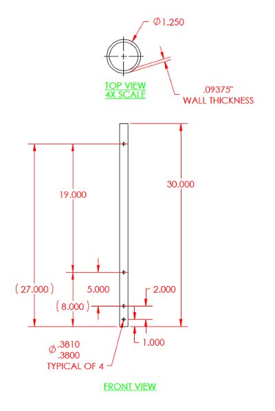
- The Pole Support, to be modeled before class per the following information:
- Material, AISI 1020 Steel, Cold Rolled
- Holes (cuts, not Hole Wizard features) are symmetrical about the center axis of the support
- Modify the dimension tolerance per the method in Project 2
- The Back Plate, to be modeled before class per the following information:
- Material, AISI 1035 Steel
- Holes as shown are symmetrical about the center plane of the plate
- Modify the dimension tolerance as shown
- Use a SolidWorks appearance based cosmetic pattern of your choice (not the default settings). Explore this on your own.

- Back Plate Support, can be downloaded at the following link: Back Plate Support
- Install per the image below, the support is coincident to the Back Plate, or the curved surface of the support surface is coincident to the curved surface of the Pole Supports and the holes line up.

- The Horizontal Wheel Mount, can be downloaded at the following link: Horizontal Wheel Mount
- Regarding the image below, use the Insertion Plane, as shown, to create a coincident mating relation to the top surface of the Pole Supports. Use other symmetric relations to fully define this part.
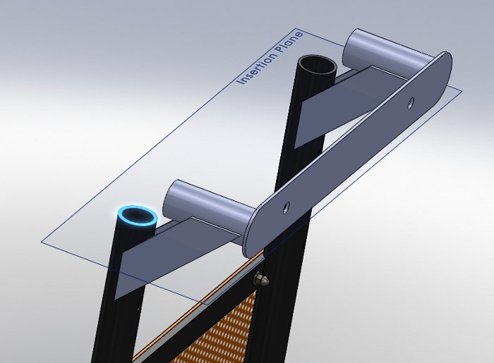
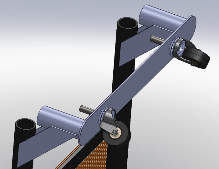
- Find and download a caster from 3D Content Central and insert it onto the Horizontal Wheel Mount.
- Find a caster without a brake and a 3/8" threaded stem.
- Mate the caster to the bottom of the Horizontal Wheel Mount, coincident with the hole provided allowing it to rotate about the stem.
| - | ||
 |
|
Week
7:
Lecture: Threaded fastener assignment, loft features from the SG book, Exploded View Drawing items. |
Evaluation:
- Click on the following link for this week's Evaluation Check List (ECL),
- print your checklist and fill it out before class.
- Threaded Fastener assignment, due by Friday at 5pm via email (details on Monday and Tuesday).
- See the Student Resources page for instructions on this assignment and related resources.
- Grading criteria follows, 30 points total
- Symmetry (2 points)
- Rename your features (3 points)
- Material (3 points)
- Head and chamfer (2 points)
- Ring shank and fillet (2 points)
- Length (2 points)
- Bottom Chamfer (2 points)
- Threaded path (5 points)
- Threaded cut (5 points)
- Thread length (4 points)
- An Exploded View drawing of your Assembly Model Assembly with Balloons and a Bill of Materials (per Project 3 in the ED book). Print this out on a B sized sheet and in the Box by 5pm on Friday. Grading criteria follows, 20 points total:
- B sized sheet landscape (3 points)
- Isometric Exploded View with Shaded With Edges SWE (3 points), explode line sketch (2 points)
- Balloons, orderly and consecutive, dimension layer (3 points)
- Bill of Materials, neat and orderly, Sheet notes layer, in the following order left to right, ITEM NUMBER, DESCRIPTION, QUANTITY, PART NUMBER, MATERIAL (others as you see fit) (4 points)
- Add view title under the view on the green Sheet Notes layer (1 point)
- Fill in the usual values in the Title Block (as iterated in Project 3) (3 points) including:
- your name
- part name
- file name
- company name
- units of measure
- dimensioning and tolerancing standard
- confidentiality statement (filled in with your company name)
- Extra Credit, a Motion Study of your Assembly Model Assembly (details on Wednesday and Thursday). Make animation (if that fails see me) and send it via email by 5pm on Friday.
- In the SG book, the Chisel, the Screwdriver and a bottle of your own design similar to what is demonstrated in the book, the bottle must have at least 5 loft profiles.
- Have the above described assignments from the SG book completed for potential evaluation in Week8.
| - | ||
 |
|
Week
8:
Lecture: Spur Gear design and Project 5 on Monday and Tuesday only. YSWUG meeting will be on Thursday which will serve for both Wednesday and Thursday's class. No class in the lab on Wednesday and Thursday. |
Evaluation:
- Click on the following link for this week's Evaluation Check List (ECL),
- print your checklist and fill it out before class.
- Spur Gear assignment, due by Friday at 5pm via email (details on Monday and Tuesday).
- See the Student Resources page for instructions on this assignment and related resources.
- Grading criteria follows, 30 points total
- Complete (6 points)
- Movement (10 points)
- Significant digits (2 points)
- Do (1 point)
- Dp (2 points)
- Dr (1 point)
- Dc (1 point)
- Dc center (2 points)
- Ta (1 point)
- Root perpendicular (2 points)
- Xc (1 point)
- Extras and Errors (1 point)
- In the ED book
- Project 5 in the ED book.
- Exercise 5.7 in the ED book.
- 4 inch nominal Ductile Iron pipe
- Provide a 3/8" Rib feature between the base and the pipe above the collar and a circular pattern of this feature 4 times around the base.
- Click here for additional information: Pipe Flange
- Have the above described assignments from the ED book completed for potential evaluation in Week8.
| - | ||
 |
|
Week
9:
Lecture: Monday and Tuesday, Geometric Dimensioning and Tolerancing (GD&T) for drawings. Final Projects. Final Project Pre-Presentations on Wednesday and Thursday. |
Evaluation:
Click on the following link for this week's Evaluation Check List Monday (ECL), or Evaluation Check List Tuesday (ECL), print your checklist and fill it out before class. Hint: know how to do the Rib and Draft features per Project 5.
Lecture:
On Monday and Tuesday we will discuss Geometric Dimensioning and Tolerancing (GD&T) and how it relates to SolidWorks drawings. Click on the link below for a zip file with the various SolidWorks files that I will be demonstrating in class: GD&T.zip
On Wednesday and Thursday we will have our Final Project Pre-Presentations. This venue will provide an opportunity for your peers to evaluate your project and provide you with some useful feedback on your progress, toolbar use and project complexity. Click on the following link for a document providing guidance for your Final Project Presentation and Pre-Presentation. Final Project Presentation Guide. Click on the following link for the Pre-Presentation Peer Evaluation form for your own knowledge. I will be providing this form in book format at the beginning of class. Pre-Presentation Peer Evaluation Form.
Assignments:
On Monday and Tuesday we will modify the Modified Tutor 2 from Week 5 and one of your parts from your Assembly Model that you have been working on throughout the quarter creating drawings related to Geometric Dimensioning and Tolerancing (GD&T) items. These 2 drawings will be due in the Box on Friday by 5pm. Read ahead and come to class informed about GD&T by checking out the Student Resources section of the Website for the appropriate information.
- For the Modified Tutor 2 part create a drawing on your B sized template with the usual drawing elements that have been required throughout the quarter, plus the following GD&T items:
- Datum A on the back face
- Datum B on the right face
- Datum C on the bottom face
- Put a dimension on the maximum width of the front cut (even though it may be driven) of 116 with a Bilateral Tolerance of no more than 116 but up to 0.10 millimeters less
- Add a Feature Control Frame on this dimension stating parallelism of 0.15 millimeters referencing Datum B and Datum C
- Change the slot length dimension to 35 with a Symmetric Tolerance of plus or minus 0.50 millimeters.
- Add a Feature Control Frame on this dimension stating perpendicularity of 0.10 millimeters at the MMC referencing Datum A.
- Regarding the dimension on the first Hole Wizard hole on the back face put a dimension on width of the hole (even though it may be driven by the Hole Wizard) and put a Limit Tolerance of plus 0.20 millimeters and minus 0.00 millimeters.
- Add a Feature Control Frame on this dimension stating the position of this hole can vary by 0.080 millimeters at the MMC referencing Datum B and C.
- For your Assembly Model part create a drawing on your B sized template plus the following GD&T items of your choice (the items below must make sense):
- At least 3 dimensions with at least 2 different types of tolerances
- At least 2 datums of your choice
- At least 2 feature control frames of your choice
- The feature control frame has to be completely filled out with material conditions referring to the appropriate datum
- Can not be the same as the above references, choose 2 unique ones of your choice.
| - | ||
 |
|
Week
10:
Lecture:
Examination on Tuesday and Wednesday, details soon to follow below
|
Examination:
We will have Examination 2 on on Wednesday and Thursday this week, the last days of the week and the quarter. The exam will be in the usual 2 parts. The written portion will be per the syllabus with about half of the questions from the previous exam and the design assignment portion will be as described below:
Design portion:
Finish modeling the the Hand Truck using the assemblies, parts, Toolbox items and the casters from 3D Content Central from the first exam plus the additional parts and assemblies as described below. Make certain that your Hand Truck model is complete per Examination 1. There will be six additional parts for this exam. Four of the six parts will be modeled before the exam and will include the Tire, Wheel Hub, Axle and Handle Bar. One of the six parts will be a Cotter Pin from 3D Content Central. One of the six parts will be modeled in class. The part names, instances and descriptions of these parts include:
- Tire (1) model before class (see instructions below)
- Wheel (1) model before class (see instructions below)
- Wheel Tire Sub-Assembly (2) model before class (see instructions below)
- Axle (1) model before class (see instructions below)
- Handle Bar (1) model before class (see instructions below)
- Cotter Pin from 3D Content Central (2) download a 1/8" sized pin of your choice
- Axle Support (2) modeled during the examination
- Parts to be modeled before the exam:
- The Tire, modeled per the following information:
- Material, Rubber or plastic of your choice
-
Drawn on the Front Plane (Right
and Top Plane symmetry) The profile of the Tire can be a different
shape than what is shown for extra credit, center to center distance has
to be what is shown and has to fit your Wheel Hub. Treads
or similar details may be considered for extra credit.

- The Wheel Hub, to be modeled per the following information:
- Right and Top Plane symmetry
- Material, AISI 316 Stainless Steel Sheet
-
Added details may be considered
for extra credit

- The Wheel Tire Sub-Assembly.
- Right and Top Plane symmetry
- Create an assembly of the Wheel Hub and Tire. Fully defined mates. Insert this subassembly into your Hand Truck assembly.
- The Axle, to be modeled per the following information:
- Right and Top Plane symmetry
- Material, AISI 1035 Steel, 1/2 inch in diameter, 19" in length, 0.05" 45 degree chamfer on the ends, 0.125" hole for a cotter pin on the ends measured 3/16" from the ends.
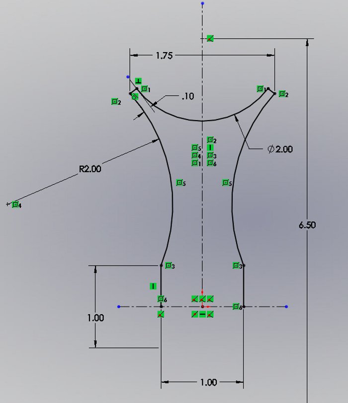
- The Handle Bar, to be modeled per the following information:
- Right Plane symmetry
- Material, AISI 1020 Cold Rolled Steel, 1 inch outside diameter with 3/32" wall thickness.
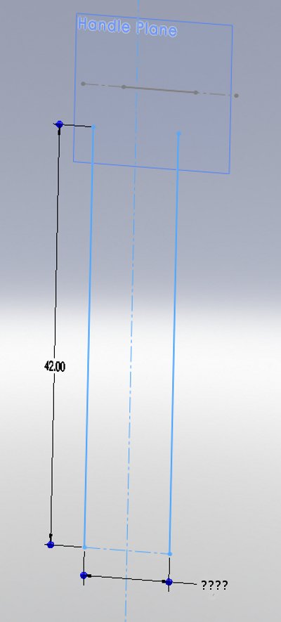
- Sweep Feature using a 3D Sketch path per the guidance below
- Draw 2 symmetric lines on the Front Plane at the appropriate distance apart from each at the defined length shown in the images below.
- On a separate plane parallel to the Front Plane sketch a symmetric line of a desired length
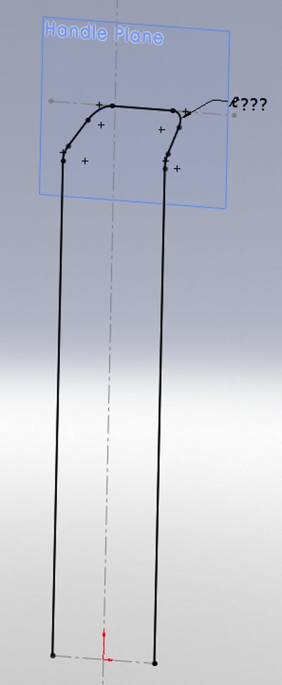
- You now have 6 endpoints that can define the endpoints of connected lines sketched in a 3D Sketch element
- Provide 4 sketch fillets with two different fillet radii of your choice.
- Cut two holes perpendicular to the Front Plane, centered on the axis in the center of the tube, on both sides of the vertical portions of this part at the same size and tolerance as on the Pole Supports 20-7/8" measured from the bottom of the Handle Bar. Also cut two holes perpendicular to the Right Plane, centered on the axis in the center of the tube, on both sides of the vertical portions of this part at the same size and tolerance as on the Pole Supports 2-1/8" measured from the bottom of the Handle Bar. In the assembly line up either of these holes with the holes on the Pole Supports or the Horizontal Wheel Mount.
- Keep your original Week 6 model intact by copying that folder into your Week 10 folder
- Save the Cotter Pin file into the folder mentioned above.
- Save the assembly of your model including your fasteners from the Toolbox into the folder mentioned above or a new one by using the "Save As" option, clicking on the "References" folder button then checking the "Save Toolbox Parts" check box. Choose a folder name and location of your choice.
| - | ||
 |
|
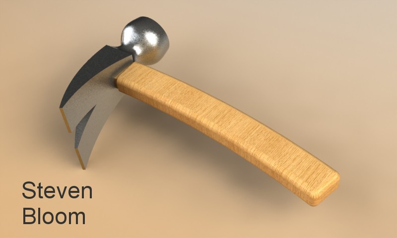
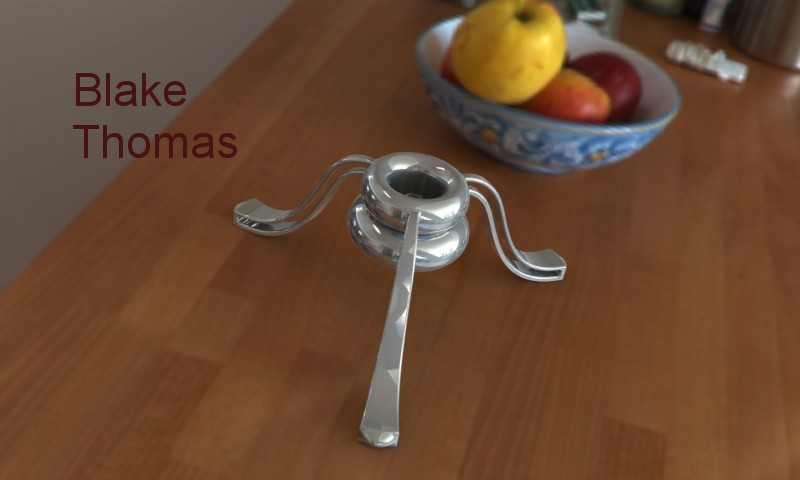
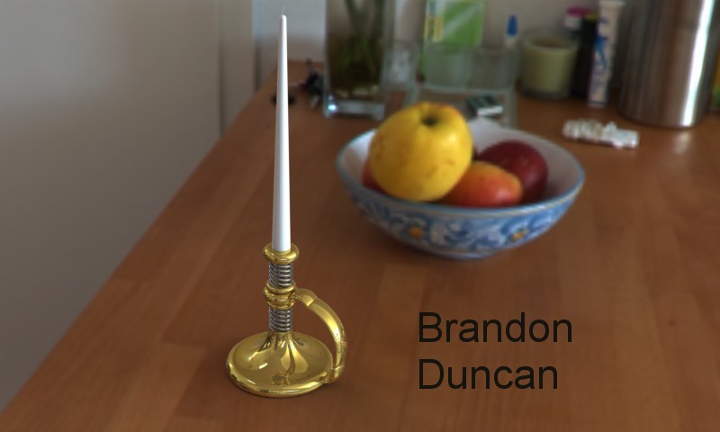
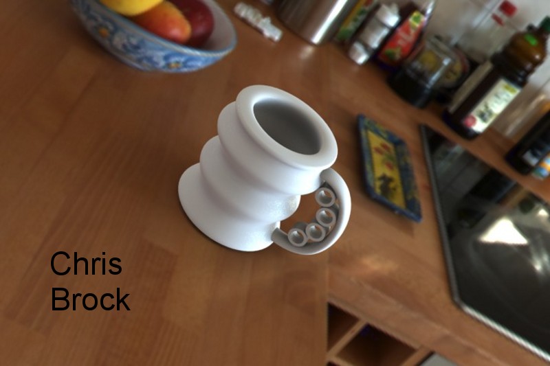
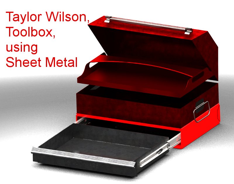
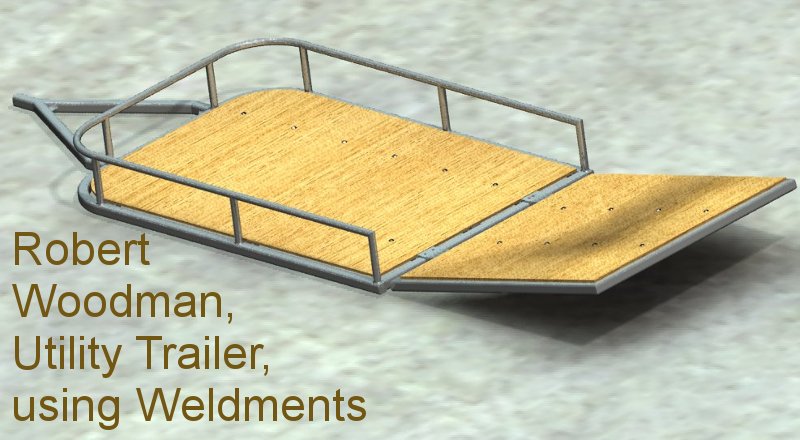
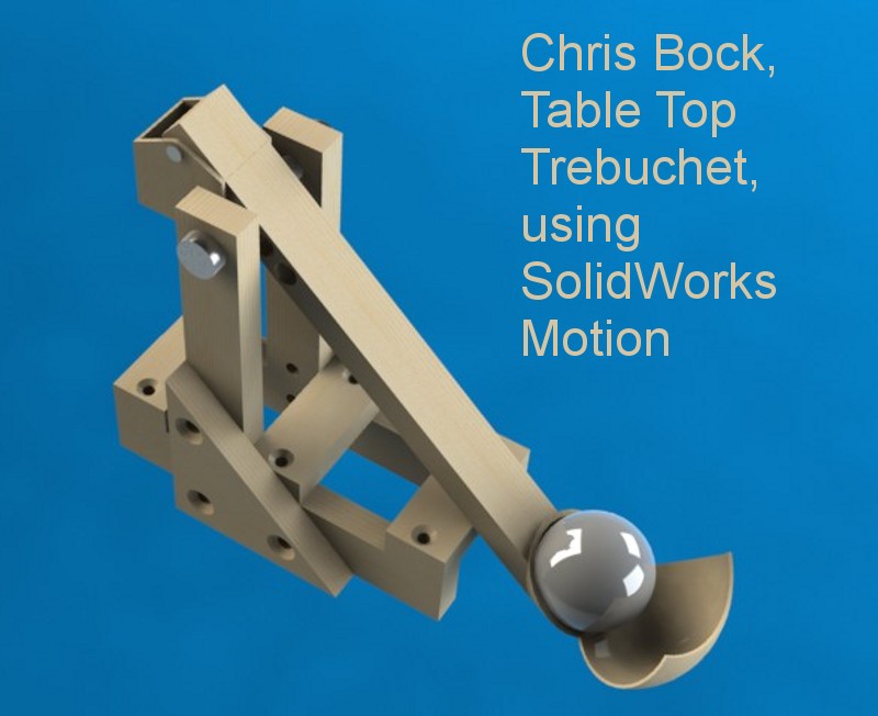
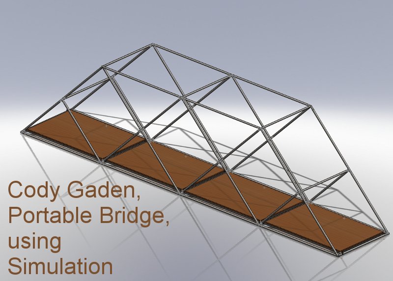
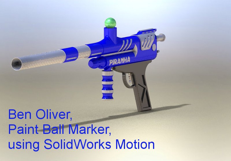
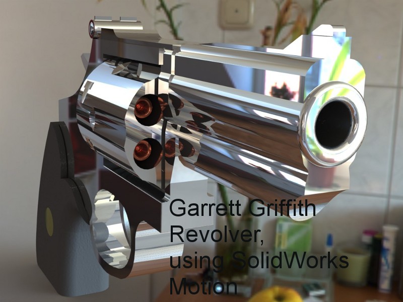
Your Final Project Images follow below

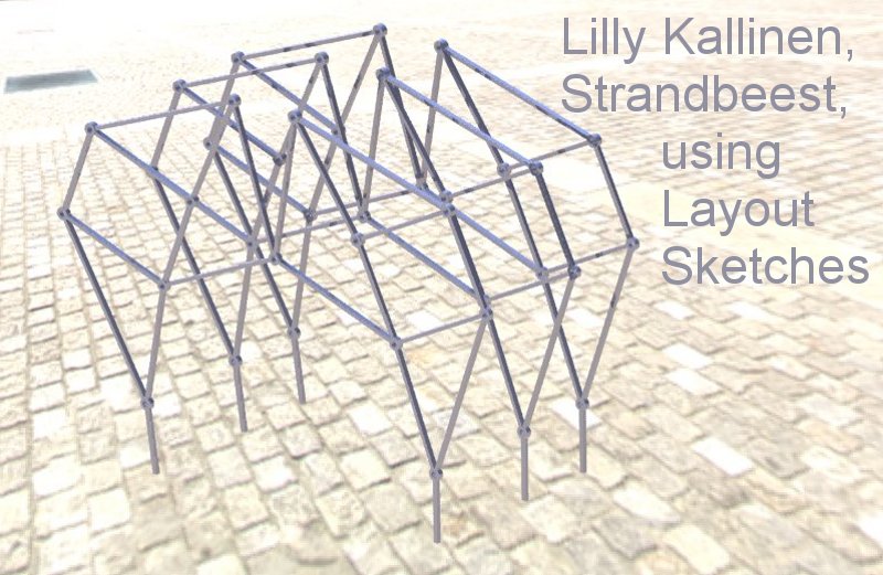

Click on the image below
for an animation


Click on the image below
for an animation

Click on the image below
for an animation
The following is a list of informational resources to be used for your Final Project:
- Final Project Abstract Information
- Final Project Student Project Categories
- Final Project Presentation Guide
- Final Project Presentation Peer Evaluation Form
- Final Project Grading Criteria
- Abstract, single page document describing what you would like to present to the class as a Final Project (20 points 10%).
- Peer Review, an evaluation on your project by your peers', (50 points 25%). Refer to the appropriate link above for additional information.
- SolidWorks toolbar or function (40 points 20%). Refer to the appropriate link above for additional information.
- Project design, a measure of modeling complexity which measures effort and competence. Refer to the appropriate link above for additional information (50 points 25%)
- Drawings (40 points 20%). These drawings can serve as a portfolio to be demonstrated to potential future employers. They will not be marked up but will be graded on an evaluation form. The drawing set will be available in the Box during the first 2 weeks of fall quarter or by special arrangement.
- Content:
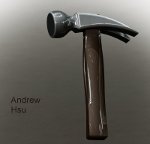
- Cover sheet with a photo real image of your assembly along with project name and designer (see example below).
- At least 3 part drawings of your choice (choose the more complex ones)
- Exploded assembly drawing with a Bill of Materials and Balloons
- Other drawings if desired but only if it adds to the information attempting to be demonstrated
- Style:
- B sized sheet, units of your choice (be consistent), printed in color
- Title Block, view, layer, logo, dimensioning and view title elements that have been required throughout the quarter
- Appropriate views including sections, auxiliary and details
- GD&T items, the following items have to make sense
- At least 4 dimensions with at least 3 different types of tolerances
- 3 datums of your choice on one or various parts
- 3 feature control frames of your choice on one or various parts
- The feature control frame has to be completely filled out with material conditions and the appropriate datum
- Cover
sheet example below (sheet list is optional by inserting a general table)

Final
Project Advice:
- Regarding the toolbar or function presentation:
- You are responsible for learning about these functions and presenting what you have learned and applied to your project. I can not be a resource for this part of your Final but can help on specific issues during class time.
- There are typically hundreds of videos, tutorials, blogs and website resources out there for what you are trying to learn, apply and present. SolidWorks tutorials (Sheet Metal, Weldments, Moldtools and Simulation) and the textbook (Sheet Metal and Mold Tools) are also resources. Check these out.
- I also have some books on Sheet Metal and Weldments if you want to borrow them. Let me know.
- Links, send me links to some sites that you find useful.
- Will Farrell sent the following regarding Curves and Surfaces:
- SolidWorks Teacher sent the following Excel links from Solid Professor which provides some tutorials on various topics that you might find helpful:
- Course Name Functionality/Subject Lesson Name
- AutoCAD to SW AutoCAD to SW Tools Embedded AutoCAD Drawing
- Core Concepts Sketcher Sketches on Faces
- Core Concepts Sketched Features Extruded Boss
- Core Concepts Applied Features Fillets
- Core Concepts Parts Symmetry A
- Core Concepts Parts Symmetry B
- Core Concepts Assemblies Coincident Mate
- Sheet Metal Sheet Metal Cuts Across Bends
- Advanced Parts Advanced Sketching Curve Through XYZ Points
- Mold Tools Mold Design Parting Surface
- Routing Routing Routing Components
- Surfacing Surfacing Knit Surfaces
- Weldments Weldments Weld Beads
- PhotoWorks PhotoView 360 Applying Appearances
- Simulation Simulation Solid vs. Shell Mesh
- SolidWorks Tutorials can be found at the following site:
- SolidWorks Blog has a student project on the modeling of a W16 piston engine at the following link:
- Here
is a link to the tutorial I was talking about;
http://www.cadtutor.net/forum/showthread.php?48664-2010-Camaro-Tutorial/page3
I know some of the other students wanted to see it, maybe you could post it on the class website so they can see it over the weekend? i have it in PDF form and i will bring it to class on tuesday.
And this is his website, there are many other excellent tutorials on here!
http://www.solidworkslessons.info/
Download SolidProfessor lesson list - SolidWorks EDU Teacher Blog
| - | ||
 |
|
|
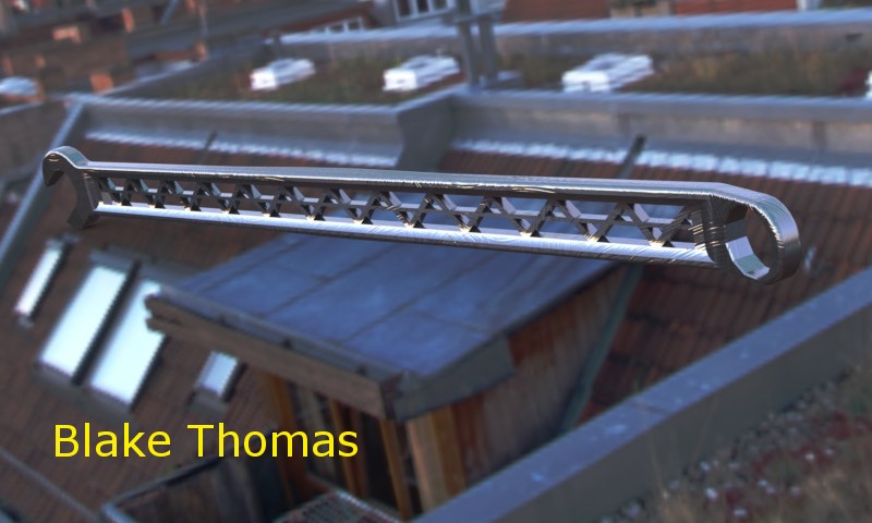
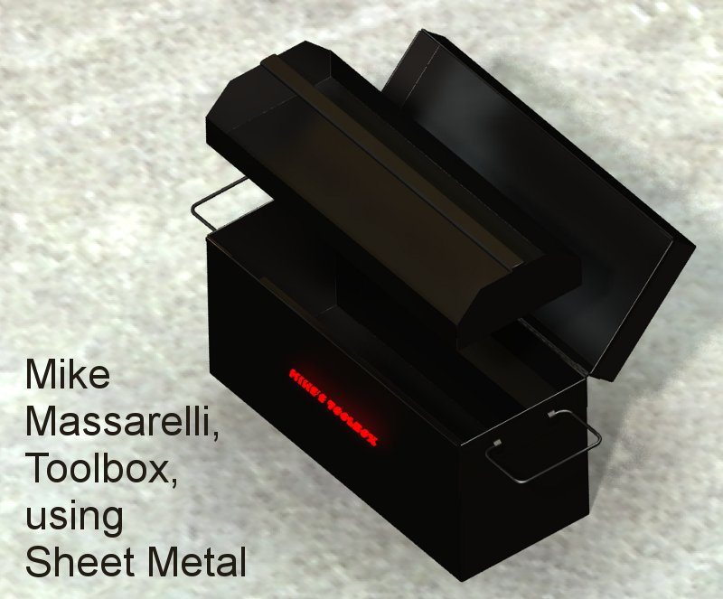
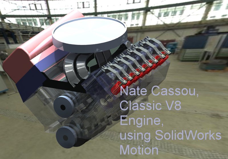
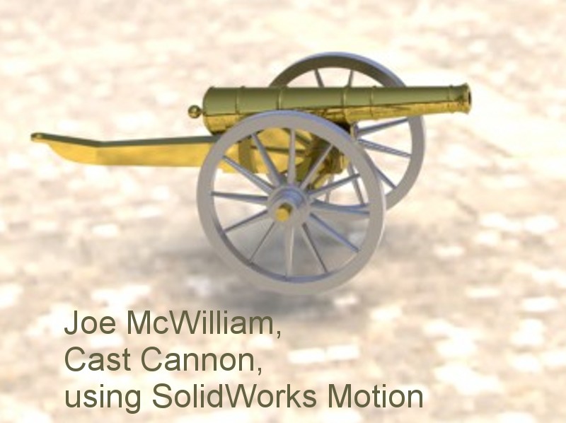
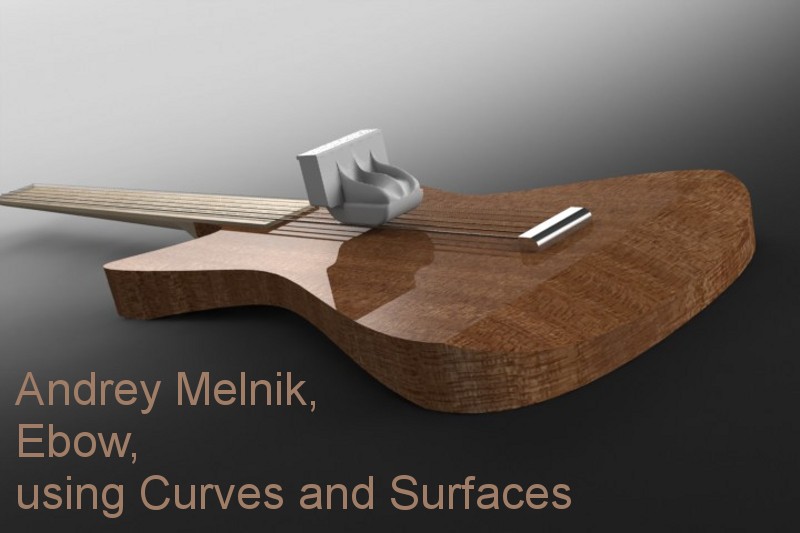
The following images display designs from this class that I believe show extraordinary effort and design or rendering qualities.
|