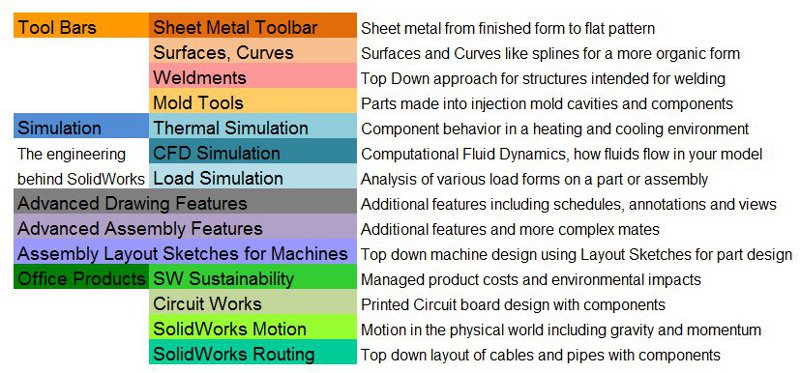
|
- |
|
|
 |
 |
-
| Week
1:
Design
Assignments due this week:
None
this week but come to the first class of Week 2 prepared by starting the
Design Assignments listed in this section below and in the Week 2 section
following.
Announcements:
Please
purchase download or otherwise acquire the following books listed below
for use in this class:
Engineering
Design... (ED)
oooo

Available
at the bookstore oooooooooooo
|
The
Ultimate GD&T Pocket Guide (UG)
Available
at the bookstore
ooooo |
Student's
Guide...
(SG)

Available
on the Student Resources page
|
d
Read
and practice ahead:
Begin
reading the engineering design book (ED) beginning with the introduction.
Then start with Project 1 designing the Plate following the steps
involved. Continue on with the Rod and the Guide.
Begin
reading the student guide (SG) from the introduction through Lesson 1 then
design the Box in Lesson 2 following the steps involved.
There
will be an evaluation on the first day of class next on these assignments.
|
Out
of Class Design Assignment details:
-
ED Book
-
Start the Plate in Project
1
-
Create the various part template
files (see the video links below)
-
SG book, Lesson 2
-
VD the Junction Box video,
see
links below.
Instructional
Videos:
|
- |
|
|
 |
|
-
| Week
2:
Design
Assignments due:
On the
first day of class this week come to class with the completed assignments
from Week 1 in preparation for your In Class Evaluation (ICE). See
details below. |
In
Class exercises and assignment details:
-
In Class Evaluation (ICE) (2
items). Click here for
your Week 2 ICE Grading Criteria (coming soon) print this out, fill
in the needed information, follow the instructions and hand it in at the
end of the evaluation. On the first day of class this week we will have
an evaluation of the models completed so far from Week 1, the Plate,
Box and Junction Box. The evaluation criteria will include:
-
Junction Box (10pts)
-
Completeness with symmetry (2pts)
-
Fully defined sketches with
dimensions (4pts)
-
Extrude, Feature Fillet, Shell,
Extrude Cut for hole (1pt each)
-
Extras and errors
-
Mounting Plate (10pts)
similar to the Plate in the ED book
-
Completeness with symmetry (2pts)
-
Correct starting plane (1pt)
-
Fully defined sketches with
dimensions (4pts)
-
Extrude, Feature Fillet, Extrude
Cut for hole (1pt each)
-
Extras and errors
-
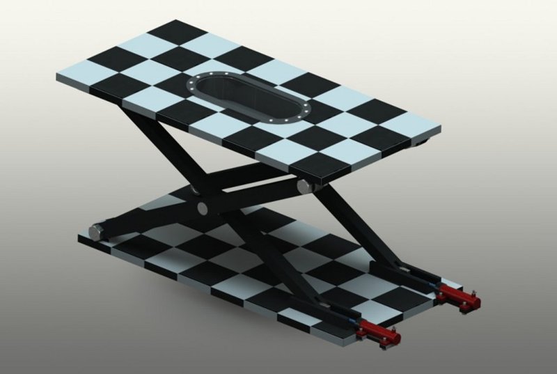
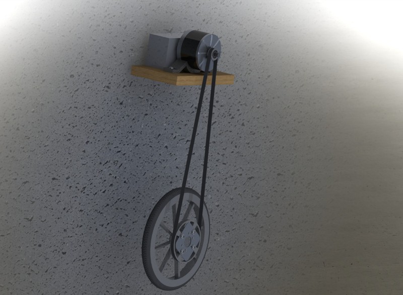
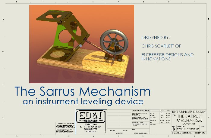
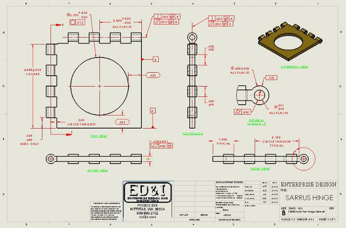
The Sarrus Mechanism Demonstration
click on the following link
for a zip file of the parts and assembly Sarrus
click on the following links
for pdfs of the part drawings.
Base
Plate
Hinge
Wheel
Mount
Wheel
Push
Rod / Pin
Out of
Class Design Assignment details:
-
Complete the Plate, start
the Rod and
Guide
in Lesson 1
-
The exercises from the end of
Project 1 on the Class Schedule
SG book, Lesson 2
VD Junction Box (and
the Section videos for the ED book exercises)
Instructional
Videos:
|
- |
|
|
 |
|
-
| Week
3:
Design
Assignments due:
On the
first day of class this week come to class with the completed assignments
from Week 2 in preparation for your In Class Evaluation (ICE). See
details below. |
In
Class exercises and assignment details:
-
In Class Evaluation (ICE) (3
items). Similar to last week: Click
here for your Week 3 ICE Grading Criteria, print this out, fill in
the needed information, follow the instructions and hand this in at the
instructor's desk at the end of the evaluation. On the first day
of class this week we will have an evaluation of the models completed from
Week 2. The evaluation criteria may include:
-
New Part 1 (10pts)
-
Completeness with symmetry (1pt)
-
Correct starting plane (1pt)
-
Material 6061 Alloy (1pt)
-
Fully defined sketches with
dimensions (1pt)
-
Extrude, Feature Fillet, Shell,
Extrude Cut for hole, Hole Wizard (1pt each)
-
Find the Mass, 4 units after
the decimal (2pts)
-
Extras and errors
-
Mystery Part 1, already completed,
to be announced during the ICE (10pts)
-
Completeness with symmetry (1pt)
-
Correct starting plane, material
AISI 304 (1pt)
-
Fully defined sketches with
dimensions (1pt)
-
Save the file then resave it
with the following name TBA (1pt)
-
Modify various dimensions, TBA
(1pt each)
-
Find the Mass, 3 units after
the decimal (1pt) Center of Mass x, y and z (2pts)
-
Extras and errors
-
Mystery part 2, already completed,
to be announced during the ICE (10pts)
Out of
Class Design Assignment details:
-
Assembly Models. This
is a graded assignment for this week. On Thursday I want a one paragraph
write up (in an appropriate engineering communication format) of what you
propose to model per the criteria below and printed before class (points
off for printing during class). The paragraph should include what
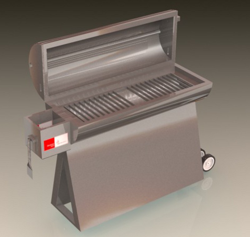
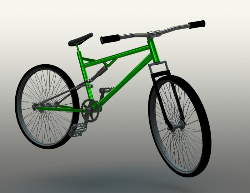
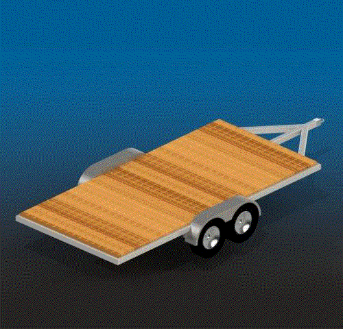
the assembly model will be called (such as Bar-B-Que, video game controller,
socket ratchet handle, conveyor belt, car, bike or similar items), what
it is used for, how it works and other descriptions then describe each
of the different part components that will be modeled and mated into the
assembly. I will discuss individually with you on Thursday what you
would like to model and give you some ideas on how to get started. Assignment
details follow:
-
Design at least 3 unique parts
with the expectation of assembling them for the next Design Assignment.
Parts in the assembly, other than the base, must be able to move, rotationally
or translationally (like a machine).
-
Base, one part has to be a base
feature to be fixed to the Origin in the assembly.
-
To have a round or rectangular
hole(s) or slot(s) or an extruded boss(es) for use as a reference for the
insertion of additional parts
-
Hole Wizard holes in the base
for mounting to some external structure
-
Parts1 and 2 (or more)
-
To be inserted on the base or
on one of the other parts
-
Must fit into the slots, holes
or bosses on the Base as described above
-
Fasteners, connectors, pins
and similar items are not appropriate parts for this assignment but can
be used.
-
Include the following features
on at least one of the parts above:
-
Fully defined sketches
-
Hole Wizard feature on a part
other than the Base
-
Linear or circular pattern
-
Include a Fastener from the
Toolbox in the Design Library into your assembly, in more than one location,
properly mated.
-
Feature using the Slot Sketch
Entity on a part
-
Evaluation:
-
A minimum level of complexity
is required for each part.
-
For the sketches of your parts
I will be looking for about 24 Sketch Relation groups, Dimensions and Reference
Geometry items on your most complex sketch.
-
For the Features of your parts
I will be looking for 6 Features or Bodies
-
3 parts will be considered for
full credit, the next 3 parts will be considered for half credit.
-
The combination of sketch elements,
features and parts will be added together, divided by 3 for a score with
a maximum of 36 points (20% more). From this score points will be
taken off for missed items in the section above or added to for extra effort
displayed.
-
Complete the Rod and
Guide
in
Lesson 1
-
Insert a cosmetic thread, of
the appropriate size, on both the front and back holes of the Rod.
-
The exercises from the end of
Project 1 on the Class Schedule
-
SG book, no exercises this week
-
SW Tutor1, in the SolidWorks
Tutorial (Getting Started) section of the Task Pane
-
Rearrange the Features so that
the front hole and the associated fillets are not influenced by the Shell
Feature (see image nearby).
-
VD The Meter Base
and
the Meter Cover and assembly below
Instructional Videos
|
- |
|
|
 |
|
-
| Week
4: We will not have class on Tuesday of this
week. I will be attending the annual SolidWorks World conference.
Continue to work on your assignments from Week 4 and Week 5.
Design
Assignments due: None this week, look for
information in Week 5 soon. |
In
Class exercises and assignment details:
-
In Class Evaluation (ICE), none
this week.
-
On Thursday
of this week I will review your your Assembly Models in class. Similar
to last week, I will visit each of you and help you on your models prior
to the Week 5 In Class Evaluation. make certain that you have enough
modeled to make this help session meaningful. See the Week 5 section
bellow for additional information on grading.
Out of
Class Design Assignment details:
-
Complete the Guide-Rod assembly,
follow the book in Lesson 2
-
Ex 2.1, look for the files on
your book CD
-
Ex 2.8
-
use the Link created
in the "Configurations, Design Tables and Equations" videos listed below.
-
Make the Base symmetric,
front and back, left and right.
-
Make the link mounts symmetric
as well and forked.
-
Be creative with your designs.
-
VD The Configurations, Design
Tables and Equations videos below.
-
SW Tutor 2 follow the
instructions in the software tutorial.
-
Complete your Assembly Model
per
the criteria in Week 3.
Instructional Videos:
|
- |
|
|
 |
|
-
| Week
5:
Design
Assignments due:
On the
first day of class this week come to class with the completed assignments
from Weeks 3 and 4 in preparation for your In Class Evaluation (ICE).
See details below. |
In
Class exercises and assignment details:
In Class Evaluation (ICE)
(3 items). Similar to previous weeks: Click here for your Week
5 ICE Grading Criteria, print this out, fill in the needed information,
follow the instructions and hand this in at the instructor's desk at the
end of the evaluation. On the first day of class this week we will
have an evaluation of the models completed from Weeks 3 and 4. Review
all of the videos that have been posted and listed on this site to ensure
that you have the following items covered properly for Week 5's evaluation.
The evaluation criteria may include:
-
New Part (20pts)
-
Completeness with symmetry (1pt)
-
Correct starting plane (1pt)
-
Material Aluminum (1pt)
-
Appearance clear (1pt)
-
Fully defined sketches with
dimensions (1pt)
-
Extrude, Feature Fillet, Hole
Wizard (1pt each)
-
Find the Mass, 4 units after
the decimal (3pts)
-
Extras and errors
-
New Assembly (using some modeled
parts from the previous weeks) (10pts)
-
Complete with all of the parts
(3pts)
-
Proper orientation of all parts
(1pt)
-
Base fixed to the origin
(2pts)
-
Properly mated, so that all
parts are fixed or fully defined (3pts)
-
Apply a scene (1pt)
-
Mystery Assembly (20pts)
-
Complete with all of the parts
(4pts)
-
Proper orientation of all parts
(1pt)
-
Base fixed to the origin
(2pts)
-
Properly mated, so that the
parts move as intended (3pts)
-
Assembly Model (30pts)
-
Criteria as defined in the Week
3 section above
Out of
Class Design Assignment details:
-
ED Book
-
Exercises 2.5 and 2.6, look
for the files on your book CD
-
SG Book
-
VD view the Sarrus Mechanism
assembly with mates, Toolbox items and an Exploded View configuration.
Apply these techniques to your Assembly Model project. See the video
section below.
-
Assemble your Assembly Model
using
appropriate mates, Toolbox items and an Exploded View configuration.
-
Assemble the 3 or more parts
of your design into a SolidWorks Assembly. Mate these using the requirements
listed below. The parts in your assembly, other than the base, must
be able to move, rotationally or translationally (like a machine).
Apply mates to achieve these functions.
-
Parts need:
-
Fully defined sketches.
-
Symmetry in construction if
the model is also symmetric about a plane or multiple planes or axes
-
To have a round or rectangular
hole(s) or slot(s) or an extruded boss(es) for use as a reference for the
insertion of additional parts
-
Hole Wizard holes in the base
for mounting to some external structure.
-
The assembly needs:
-
Fully defined except for the
parts that need to move
-
At least 3 different Items from
the Toolbox inserted in multiple locations
-
Insert a Limit or Screw Mate
or an Advance or Mechanical Mate of your choosing.
-
Explode View configuration
-
Exploded Line Sketch for all
components
Instructional Videos:
|
- |
|
|
 |
|
-
| Week
6:
Design
Assignments due:
On the
first day of class this week come to class with the completed assignments
from Week 5 in preparation for your In Class Evaluation (ICE). See
details below.
Check
the section on "Out of Class Design Assignment Details" below. including
information on your Final Project Abstract and categories.
Deadlines:
Friday:
Week 6 ICE redos, Your Assembly Model Assembly per the ICE
checklist. There will no redos for this so make certain that you
have it correct in class on Thursday. |
In
Class exercises and assignment details:
In Class Evaluation
(ICE) (3 items). Similar to previous weeks: Click here for your Week
6 ICE Grading Criteria and the Gas
Regulator Drawing, print these out, fill in the needed information
including your name, follow the instructions and hand both of these documents
in at the instructor's desk at the end of the evaluation. On the
first day of class this week we will have an evaluation of the models completed
up to Week 5. Review all of the videos that have been posted and
listed on this site to ensure that you have the following items covered
properly for Week 6's evaluation. The evaluation criteria may include:
-
New Part (20pts) more information
soon
-
Completeness with symmetry notice
the location of the Origin.
-
Correct starting plane, front
-
Material Aluminum
-
Fully defined sketches with
dimensions
-
Correct features
-
More information soon
-
New Assembly (using some modeled
parts from previous weeks) (20pts)
-
Complete with all of the parts
(3pts)
-
Take the unsymmetrical parts
and make them symmetrical (3pts)
-
Rename the Part (1pt)
-
Part fixed to the origin and
on top of the Feature Manager Tree (2pts)
-
Modify the Part so that the
Hole Wizard Holes match the options in the other Part (2pts)
-
Install or redefine the mates
for the Part (2pts)
-
Length of the fastener.
Enter that Length here ________________ (2pts)
-
Properly mated and everything
fully defined including fasteners (5pts)
-
Extras and errors
-
Assembly Model (30pts)
Criteria as defined in the
Week 5 section above
-
Out
of Class Design Assignment details:
-
ED Book
-
Final Project Abstract
-
Click here for a grading guide
on your Final
Project Abstract
-
Choose a toolbar or function
to study practice and then demonstrate during your Final Project
presentation from the categories or subcategories listed below, if you
want to choose something different from what is listed please see me.
-
Drawing Template File information
Back
Up:
Follow the book with the
following exclusions, inclusions and modifications as listed below.
-
Create the Millimeter file first,
save it, then resave it as your inches file making the appropriate changes
for the units. Start from the beginning of the project and follow
all of the steps listed.
-
Page 3-9, the bottom of the
page, when it discusses the units make certain that you also assign inches
as the "Dual Dimension Length" with 3 units after the decimal (like we
have been doing all quarter)
-
Save your file to "DRAW-MM-ANSI"
in your template folder.
-
Page 3-10, top of the page,
make certain your font and text size are as described (the default annotation
size is set at about 1/8" which is appropriate for large text, notes and
smaller text will be about 3/32", we will use this when needed in class)
-
Page 3-10, middle of the page,
change the bent leader to a length of 2mm as opposed to the default value.
You will find this location using information in the image below.
-
Page 3-11, top of the page,
Create the following layers and setting as listed below:
-
name: Titeblock-Border, color:
Dark Blue
-
name: Dimensions, color: Red
-
name: Sheet Notes, color: Green
-
name: Hidden Dims, color: Blue
(turn off this layer)
-
Page 3-13, middle of the page,
know about "Edit Sheet" and "Edit Sheet Format" for the test.
-
Page 3-14, bottom of the page,
enter your company name not D&M and the font size and style of your
choosing, make certain it fits the space it is located in on the Title
Block.
-
Page 3-15, bottom of the page,
insert the drafting standard notation ANSI Y14.5 in addition to and after
the text that is provided
-
Page 3-16, top of the page,
make certain that you change the millimeter values to inch equivalents
when you make your inch template file, you will be graded on this!
-
Page 3-17, top of the page,
create a logo using the following guidelines in a style of your choosing.
-
Include a company name, address,
phone number and website address below, nearby or included in your logo.
-
Choose a name and style that
fits your career ambitions or personality. You may design something
in SolidWorks, AutoCAD, Paint, Photoshop, Word or another design program.
Use the following criteria:
-
Your logo must be unique, no
credit for someone else's work
-
An image
-
Inserted to the left or in between
the Proprietary and Confidential box in the titleblock
-
Draw sketch lines around it
(on the Titeblock-Border layer) and make the logo fit the space and look
neat
-
Does not have to look 3D or
in color (they usually are not in color on engineering drawings)
-
Include some graphical styling
including various line sizes, fonts, hatching and other techniques
-
extra credit for extra design
styling
-
Below is my logo and would represent
a design that meets the criteria described above.
-
Below are some additional logos
from various engineering and architectural drawings that I have found over
the years. These were designed in AutoCAD.
-
Save your file then resave it
as your inch template, change all of the annotations and settings to inches
then save your file.
-
Assembly Model Parts and Assembly
Drawing information
Back
Up:
Drawing assignments.
Once you have completed your drawing template files you can use them for
your Assembly Model parts and assembly drawings Design Assignments (explained
below) due this week.
-
Insert the "Guide" and "Guide
Rod Assembly" for an Exploded View, as described in the rest of Project
3. Concurrent with the "Guide" and "Guide Rod Assembly" insert your
more detailed part from your Assembly Model and your Assembly Model assembly
design from last week into two similar drawings using the same parameters
as described in the book.
Instructional Videos:
|
- |
|
|
 |
|
-
| Week
7:
Design
Assignments due:
Exam
this week, check back for details.
Deadlines:
Monday:
ICE, drawing files from Week 6 as part of your weekly ICE and the Mystery
Part. We will discuss your Final Project ideas.
Tuesday:
First Examination, Final Project abstract due
Thursday:
Hand back drawings from Monday's ICE for redos.
Friday,
5pm: Redos on your drawing files. |
In
Class exercises and assignment details:
In Class Evaluation
(ICE) (2 items). Similar to previous weeks: Click here for your Week
7 ICE Grading Criteria and the Wagon
Handle Mount drawing print these out, fill in the needed information
including your name, follow the instructions and hand these in at the instructor's
desk at the end of the evaluation. On the first day of class this
week we will have an evaluation of the drawings that you completed in Week
6. Review all of the videos that have been posted and listed on this
site to ensure that you have the following items covered properly for Week
7's evaluation. The evaluation criteria will include:
-
Assembly Model Part Drawing,
print before class, points off for printing during class and even more
after class (15pts)
-
Front, Top, Right, Views (3pts)
-
Section View (1pt) Auxiliary
View (1pt), Detail View (1pt)
-
Appropriate annotations for
the sections, details and auxiliary views (1pt)
-
Views laid out with equal spacing
between left right and top and bottom (1pt)
-
Appropriate dimensions (3pts)
neat and orderly (2pts) Dimension layer (1pt)
-
View labels for each view (1pt)
on Sheet Notes layer (1pt)
-
Errors and Extras
-
Assembly Model Assembly
Exploded Drawing, print before class, points off for printing during class
and even more after class (15pts)
-
All Parts (3pts)
-
Exploded view, shaded with edges
(2pts)
-
Explode line sketches (1pt)
-
Explode neat, orderly, easy
to read (1pt)
-
Bill of materials with Item
Number, Description, Material, Part Number and Qty columns filled in (3pts)
-
BOM neat and orderly (1pt)
-
Balloons (1pt) with circular
split line for Item Number and Qty (2pts)
-
Balloons neat and orderly (1pt)
-
Errors and Extras
-
Title Block Items (10pts)
-
All items apparent (1pt)
-
Company name filled in and in
border (1pt)
-
File name fits (1pt)
-
Unless Otherwise Specified section
filled in properly (1pt)
-
Interpret Geometric Tolerancing
section filled in properly (1pt)
-
Logo, effort, unique, (2pts)
fills the box, company name, address, phone number, web address (2pts)
-
Proprietary section filled in
(1pt)
-
Mystery Part to be used for
the exam on Tuesday, no redos on this part (20pts)
-
Completeness with symmetry,
notice the location of the Origin. (4pts)
-
Material AISI 1020 (1pt)
-
Correct starting plane, top
(1pt)
-
Fully defined sketches with
dimensions (2pts)
-
Various features (6pts)
-
Rename your features (not Hole
Wizards or fillets) (2pts)
-
Find the Mass _________, precision
at 3 units after the decimal (4pts)
-
Find the Center of Mass at 3
units after the decimal, x________, y________, z________ (3pts)
-
Extras and errors
Examination
details:
You
will have your first examination on Tuesday of this week in 2 parts.
The written portion will be per the syllabus and the design assignment
portion will be as described below:
-
Model the little red wagon below.


-
The Axle, 1/2 inch by
24 inches, "AISI 1020 Steel, Cold Rolled"
-
Download the following file
for your Wagon
Wheel Mount
-
Create a sub-assembly using
the Wagon Wheel Mount (front and back configuration), Wheel Tire
sub-assembly and the Axle to save time during the exam.
-
Download the following file
for your Handle
Bar
-
Model an Axle Hub Cap,
your design, mate symmetrically over the axle without clearances or interferences
and fully defined to the Axle. Extra credit.
-
Wagon Handle Mount Pin,
mate symmetrically without clearances or interferences and fully defined
to the Handle Bar. Extra credit.
Instructional Videos:
|
- |
|
|
 |
|
-
| Week
8:
Schedule
for this week:
Threaded
Fastener assignment will be covered in class on Thursday.
The
Spur Gear Design assignment: Follow the videos at the links below.
Tuesday
we will go over the results of the first exam. We will then spend
the rest of the class period demonstrating 3D printers. Additional
details below.
Friday,
hand in your 3 revolved features parts and one image by 5pm. |
In
Class exercises and assignment details:
In Class Evaluation
(none this week because of the holiday)
Out
of Class Design Assignment details:
-
SG Book,
-
Lesson 9, 3 revolved parts,
design 3 revolve features parts per the requirements below, parts and images
due by Friday of Week 8:
-
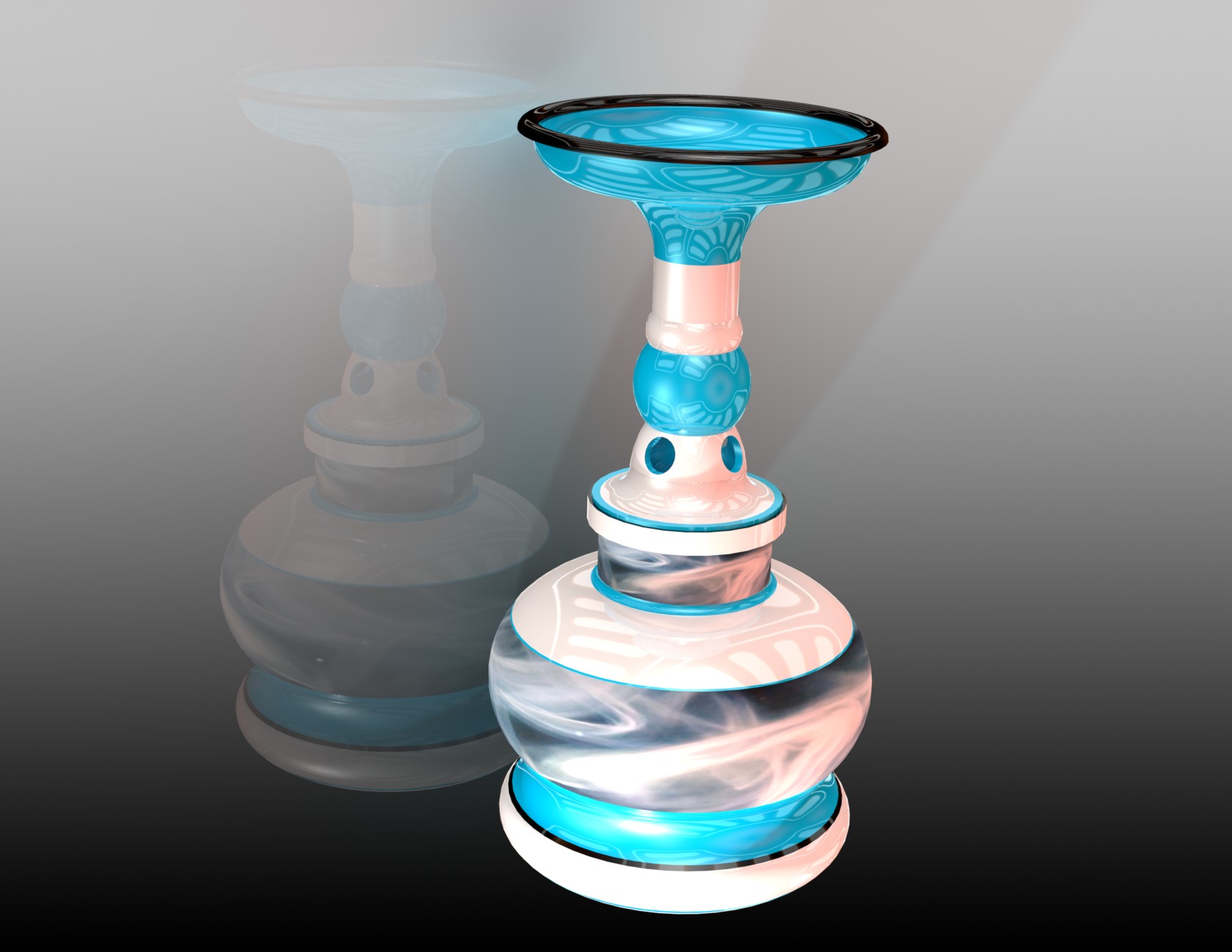
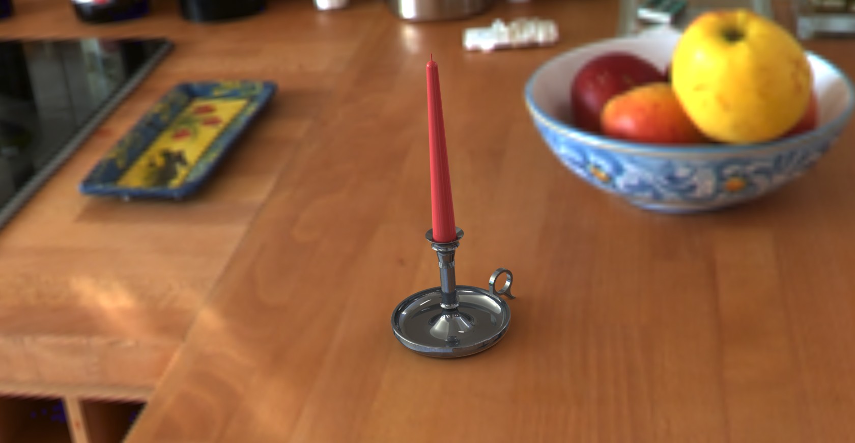
The first part needs to resemble
a vase or candlestick similar to the image on page 111
-
Two other parts parts using
a revolved feature of your choice (bowls, drinking glasses, wine glasses,
cups, trays, tops, lamps, lighting fixtures, hub caps, lids, fasteners,
etc... anything that can be created using a revolved feature)
-
All part sketches are fully
defined
-
Choose your best part to make
a photo real image, Using PhotoView 360 (see videos below), per the following
requirements. The class will vote on the best image for the Week
9 ICE:
-
Model needs to fill the image
-
Using the PhotoView 360 Options
choose the following:
-
choose "Best" resolution
-
jpg format
-
800 pixels wide, variable height
as needed
-
In the Display Manager tabs
select
-
Appearances, choose an appearance
if you don't have or don't like the material selected on the part
-
Decals only if appropriate,
if chosen do not use the default ones create your own for extra credit
-
Scenes, choose a scene
-
Lights, add custom Spot or Point
light with settings other than default, make certain you turn these on
for PhotoView 360
-
Define a camera position and
use this for your image
-
Extra credit for extra effort
and extra images
-
Lesson 10, models as shown,
Chisel and Screwdriver only
-
ED Book
-
Projects 4 (from Week 7) and
5, skip the part on Mold Tools in Project 4
-
Ex 4.4 Screw and Ex 4.9 Plate,
model as shown. Your Week 8 ICE will involve modifications to either
one of these parts.
-
Ex 5.7, Flange Pipe, information
on this soon and will involve revolve, sweep and lofted (using guide curves)
features.
-
Threaded Fastener Assignment
(evaluated as part of Week 10's ICE)
-
Spur Gear Design Assignment
(evaluated as part of Week 10's ICE)
Instructional Videos:
|
- |
|
|
 |
|
-
| Week
9:
Design
Assignments due:
On the
first day of class this week come to class with the completed assignments
from Weeks 7 and 8 in preparation for your In Class Evaluation (ICE).
See details below.
We will
cover Geometric Dimensioning and Tolerancing this week, details soon.
The Yakima
SolidWorks Users Group meeting is on Thursday, this is an extra credit
assignment, let me know if you me to coordinate carpooling. Visit
the website for additional information: YSWUG |
In
Class exercises and assignment details:
In Class Evaluation
(ICE) (3 items and an extra credit item). Similar to previous weeks:
Click here for your Week
9 ICE Grading Criteria and the Iron
Pipe drawing, print these out, fill in the needed information including
your name, follow the instructions and hand these in at the instructor's
desk at the end of the evaluation. On the first day of class this
week we will have an evaluation of the models that you completed in Weeks
7 and 8. Review all of the videos that have been posted and listed
on this site to ensure that you have the following items covered properly
for Week 9's evaluation. The evaluation criteria may include:
-
Vote on the Revolved Features
part image from Week 8 in the Design Gallery below that you
find exceptional. Vote for your first 3 choices by number.
-
Screw part (20 pts),
referring to the image make modifications to your part that you designed
last week.
-
Completeness with symmetry,
notice the new location of the Origin. (4pts)
-
Material, AISI 316 Annealed
Stainless Steel Bar (1pt)
-
Correct starting plane, Front
(2pts)
-
Fully defined sketches with
proper dimensions and sketch relations (2pts)
-
Proper precision on appropriate
dimensions (2pts)
-
Rename your features (2pts)
-
Find the Mass, precision at
4 units after the decimal 0.0053 lb (4pts)
-
Find the Center of Mass at 4
units after the decimal
x 0.0000 in,
y -0.8792 in, z 0.0000 in (3pts)
-
Extras and errors
-
The Plate, (20pts)
-
Completeness with symmetry,
location of the Origin (2pts)
-
Material (1pt)
-
Correct starting plane (1pt)
-
Fully defined sketches with
proper dimensions and sketch relations (2pts)
-
Rename your features (1pt)
-
Find the Mass, precision at
4 units after the decimal 217.7190 g (2pts)
-
Find the Center of Mass at 4
units after the decimal
x 140339 mm, y 7.4020
mm, z 0.0000 mm (3pts)
-
Change A, B and C (3pts)
-
Find the Mass, precision at
4 units after the decimal 699.6520 g (2pts)
-
Find the Center of Mass at 4
units after the decimal
x 17.3962 mm, y 10.1655
mm, z 0.0000 mm (3pts)
-
Extras and errors
-
The Screwdriver, SG (10pts)
-
Completeness with symmetry (1pt),
locate the origin between the handle and the shaft. (1pt)
-
Fully defined sketches with
proper dimensions and sketch relations (2pts)
-
Handle color (1pt)
-
Rename your features (1pt)
-
Proper Loft Feature (2pts)
-
Loft Start/End Constraints,
start Tangency to Face end Normal to Profile (2pts)
-
Extras and errors
Iron Pipe (30pts)
you can get started on this now (if you read this before the ICE on Monday
as you should). Check out the last video in the Week 8 section above
titled: 149.
Creating a Lofted Boss/Base on a Simple Part, Options, Guide Curves
you'll need to know about Lofts and Guide Curves for this portion of this
evaluation. The pipe is a nominal 6 inch cast iron pipe (look up
the OD and ID dimensions). Pipe is 24 inches long including the flange.
I would suggest modeling in the order shown
-
Completeness with symmetry,
location of the Origin (4pts)
-
Material, Ductile Iron (2pts)
-
Correct starting plane, Right
(2pts)
-
Use a value for the Outside
Diameter of a 6 inch cast iron pipe from the Mueller Co (2pts)
-
Loft Feature for the taper on
the flange per the drawing using guide curves (2pts)
-
Hole Wizard Hole, 13/16, Through
All, on a 11.925 hole circle (2pts) circular pattern (2pts)
-
Cut the Inside Diameter using
data from the Mueller Co (2pts)
-
Sweep Cut using the profile
shown for a pipe gasket (3pts)
-
Find the Mass, precision at
4 units after the decimal 90.6067 lb (3pts)
-
Find the Center of Mass at 4
units after the decimal
x 6.8736 in, y 0.0000
in, z 0.0000 in (6pts)
-
Extras and errors
-
The Mystery Extra Credit Part,
(10pts), chosen from either Project 4 or 5
-
Completeness with symmetry (4pts),
location of the Origin (1pt)
-
Material (1pt)
-
Correct starting plane (1pt)
-
Fully defined sketches with
proper dimensions and sketch relations (3pts)
Out of
Class Design Assignment details:
GD&T drawing
-
Create a drawing of one of your
parts for your Final Project using Geometric Dimensioning and Tolerancing
items learned from this week. See the ICE section in Week 10 for
additional information.
Instructional Videos:
|
- |
|
|
 |
|
-
| Week
10:
Design
Assignments due:
I will
extend the deadline for redos from Week 9 to Thursday at 5pm of Week 10.
Mass and Center of Mass values can be found in the Week 9 section above.
On the
first day of class this week come to class with the completed assignments
from Weeks 8 and 9 in preparation for your In Class Evaluation (ICE).
See details below.
Schedule:
Monday:
ICE completed before class, work on Final Projects for the balance of the
class period.
Tuesday:
Final Project Pre-Presentations, plan on spending about 2 minutes presenting
your project to the class. Work on Final Projects for the balance
of the class period.
Thursday:
Redos from Week 9 due by 2pm, markups in the Box.
Exam
2, the CSWA exam. Arrive between 2pm and 3pm. No late arrivals without
penalty. Once you start the exam you have 3 hours to complete it,
details below.
Friday:
Redos from Week 10 due by 5pm, markups in the Box. |
In
Class exercises and assignment details:
In Class Evaluation (ICE)
(4 items). Similar to previous weeks: Click here for your Week
10 ICE Grading Criteria, print this out, fill in the needed information
including your name, follow the instructions and hand these in at the instructor's
desk at the beginning of class. On the first day of class this week
we will have an evaluation of the assignments that you completed in Weeks
8 and 9. Review all of the videos that have been posted and listed
on this site to ensure that you have the following items covered properly
for Week 10's evaluation. The evaluation criteria will include:
-
Threaded Fastener Project
(20 pts) refer to the Grading Criteria for additional information, available
at the link above.
-
Spur Gear Design Assignment
(40
pts) refer to the Grading Criteria for additional information, available
at the link above.
-
The Iron Pipe GD&T
Drawing ED 5.7 (30 pts) Using the description below add the various Geometric
Dimensioning and Tolerancing text and symbols to a new drawing of your
Iron Pipe assignment from Week 9. Refer to the Grading Criteria for
additional information, available at the link above.
-
Final Project Part GD&T
Drawing (30 pts) From your Final Project chose a part of your choice and
create a new drawing. Refer to the Grading Criteria for additional
information, available at the link above.
-
The New Part and
GD&T Drawing, to be announced (30pts) We will work on
your Final Projects on Monday instead of a modeling assignment during the
In Class Evaluation. The assignments as listed above will be due
at the beginning of the class period.
-
Exam 2, the CSWA exam.
The following 5 items need to be covered for you to take and get credit
for this exam:
-
Click on the following link
to download your: Tangix
VirtualTester Program. Download and install this program on your
classroom computer on the day of your exam, Thursday.
-
Click on the following link
to get a list of your VirtualTester
Voucher Codes referencing the last 4 digits of your student ID number.
-
Click on the following link
to create a VirtualTester
account, using your email address, so you can receive and publish your
certificate (a requirement for taking and getting credit for this exam).
-
Click on the following link
for a video demonstration on how to get published (a requirement for getting
credit for this exam):
-
Send me your certificate in
pdf format so I can post it on the website (a requirement for getting credit
for this exam).
Out of
Class Design Assignment details:
Work on your Final
Projects
Instructional Videos:
Information soon
|
- |
|
|
 |
|
-
| Final
Project and presentations, Wednesday, March 13, 2pm to 4pm in
the CAD Lab.
Visit
the links in this section for information on your Final Project. |
Click
on the following links referencing you Final Project:
Presentation
Guidelines: Click on the following link for a document
providing a suggested guideline for your Final Project Presentation. Final
Project Presentation Guidelines
Peer
Evaluation: Click on the following link for a copy
of the presentation Peer Evaluation. Final
Project Peer Evaluation
Evaluation
check list: Use this as a guide for preparing for
your Final Project and presentation: Final
Project Grading Criteria
Sample
Drawing Images: View the images below and use them
as a guide to layout your own sheet set.
-
-
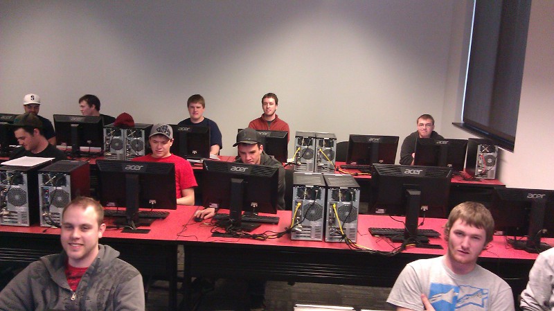
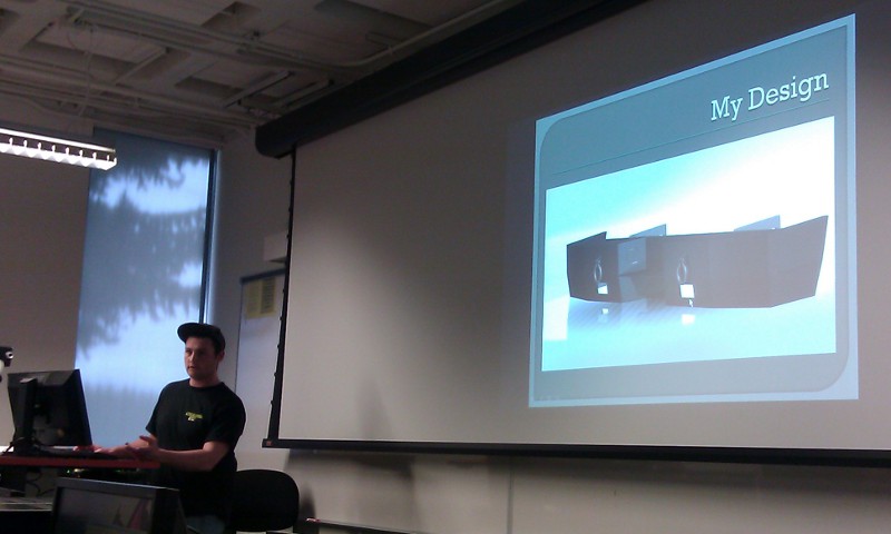
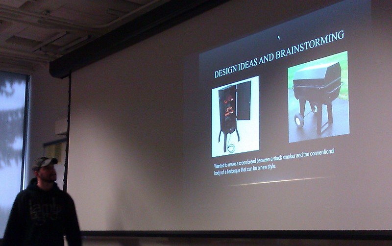
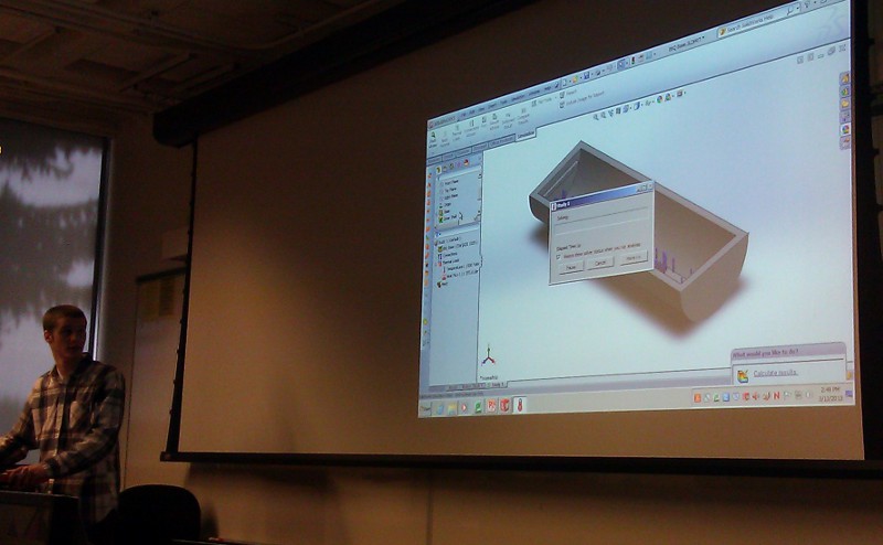
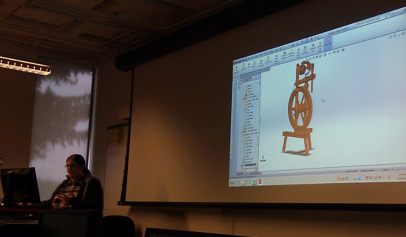
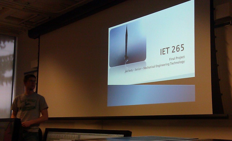
Some
images of your Final Project Presentations
Back
|